DEWBOT III Arm
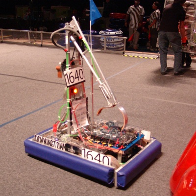
Dewbot III ended up with an effective arm for scoring, but this arm had a difficult birth.
The Arm used on Dewbot III has three articulations:
- A hinge shoulder driven by a pneumatic cylinder
- A hinge elbow driven by motors and monitored via potentiometer
- A gripper driven by pneumatic cylinder
Original Arm Mechanics
The Shoulder articulation was used to deploy the arm for play from the robot's initial staring position. The pneumatic cylinder (Parker 1.50DPSR8.0 -1½" diam x 8" stroke) was depressurized and in a neutral position with the shoulder upright for the start of competition (this kept the robot within the FRC starting envelope dimensions). At the start of Autonomous Play, DEWBOT III's compressor came on and the Shoulder deployed to the robot rear position, lifting the gripper in the process. To play, the Shoulder was normally actuated to the forward position. The Shoulder could be switched back and forth during the game to allow bi-directional play (picking up ringers on one side of the robot and scoring on the other) or to manage center-of-mass when climbing ramps at the match end for bonus points. Bi-directional play was seldom used in practice.
Dewbot III's elbow was driven by a pair of Nisso-Denso motors (L & R) with a 4:1 "gear" reduction via 10 & 40-tooth timing belt pulleys. A 270° potentiometer provides elbow angle information.
The original Gripper was a simple pneumatically-actuated vertically-oriented claw which grabbed the ringers center-to-outside.
Both arm sections were fabricated from Aluminum tubing, braized/welded with Zinc (like the frame). This produced a strong, lightweight arm. This joining method was satisfactory.
The first-generation Gripper proved to be awkward. It was difficult to hang the ringers on the Rack and especially difficult to successfully disengage afterwards. This Gripper was used only during DEWBOT III's first competition (Pittsburgh) before being replaced with an improved design.Improved Gripper
Following Pittsburgh, an improved gripper was designed by Ed Faller. The improved Gripper had two long fingers which spread horizontally and it gripped the OD of the Ringer torus, rather than from inside to outside. A high-friction webbed covering on the fingers improved the grip.
Gripping just the Ringer OD leaves the Ringer hole clear of robot parts. This makes scoring easier. It especially avoids interference with the Rack while disengaging after hanging a Ringer. DEWBOT III's scoring performance and competition ranking improved dramatically with this improvement.
The improved Gripper employed a Bimba SR-178-DP (1½" diameter; 8" stroke) for actuation. This cylinder was supplied from a second regulator to comtrol the gripping force and thereby avoid collapsing the Ringers.
Thanks Ed!
Alternative Arm Design
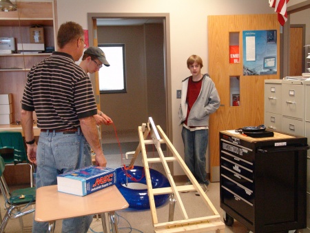
One of the Team's "process" problems in 2007 was our failure to make a decision early in the build decision between two competing Arm designs. As a result, an Alternative Arm was developed throughout the build season and (briefly) mounted on DEWBOT III.
The Alternative Arm was designed to be able to reach the uppermost targets on the Rack (and the lower as well). It operated biaxially - intended to pick up Ringers on one side of the robot and hang the on the other. The arm had four articulations:
- A rotating shoulder on the top of a fixed Stantion (powered by two FisherPrice Motors with Gearboxes and a further 16:1 reduction using timing belts).
- An inner 24 inch extension (pnuematic)
- An outer 24 inch extension (pneumatic)
- A gripper (pneumatic)
A key drawback of the design was its weight and especially the moment arm at the shoulder rotation. This was greatest with both extensions out and the Arm horizontal. This large moment arm required a mechanical brake to hold the Arm in place when not being driven.
The Arm used 80/20 profiles and slides.
The Alternative Arm was designed in CAD using AutoDesk Inventor. This was Team 1640's first use of AutoDesk Inventor.
Another first was the use of full-scale paper templates (paper dolls) as aids to cutting and drilling parts. This was necessary as the Alternative Arm required a greated degree of precision in fabrication than we've needed in the past.
Both techniques (Inventor & paper dolls) continue to be part of the Team 1640 Tool Kit.

