DEWBOT V Drive Train
Dewbot V possesses an awesome drive-train. Both agile and powerful. It's hard to score on us. We can push most opponents around. We play great defense. This is a true driver's robot. More agile than suited to straight runs.
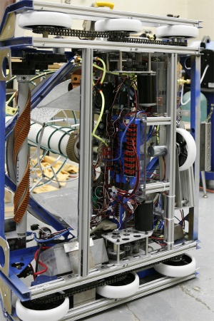
A wide 6 Wheel Drive (6wd) drive-train with the chassis oriented wide was selected for this year’s robot on the basis of providing superior maneuverability on a low-friction surface.
Wheelbase is 20.25” (long) x 33.25” (wide). Center of Mass (for the Robot) is about 9” above the Playing Surface and about 2” aft of chassis center.
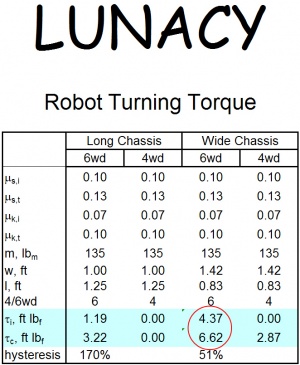
The selection of a wide 6wd chassis (in lieu of the long 6wd chassis which had been under development throughout the Fall) was based on calculated robot turning torque at Lunacy's unique low friction coefficients. Not only were friction coefficients low, but the in-line friction coefficients were noticably lower than the transverse (published in KOP, but we didn't really believe this until we tested the static and dynamic coefficients ourselves).
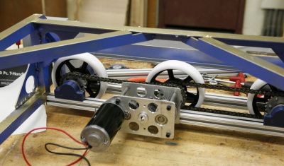
Drive-train is Tank, with independent Left and Right drives. For each side, Middle wheels are direct-driven by custom gearboxes. Front and Rear wheels are slave-driven from the middle wheels via independent chains, minimizing the impact should the robot lose a chain.
Direct-drive gearboxes are based on AndyMark Shiftboxes modified to: 1) add an additional axle and reduction for direct drive; and 2) disable the shift mechanism (unnecessary for Lunacy). (1) CIM motor is used per drive. Overall reduction ratio (CIM to Wheel) is 24:1, providing a maximum speed of 5.9 ft/s and more than adequate torque for turning.
Open the Microsoft Excel Dewbot V drive-train mathematical model.
A novel 7th Wheel is provided at the center-rear of the chassis, driven independently via a direct Globe Motor. The 7th Wheel is beneficial for 1) rotating (spinning) the robot in-place; and 2) braking. The 7th Wheel is oriented perpendicular to the 6wd and may be engaged or disengaged by the Pilot/Driver. When disengaged (default), the 7th Wheel is raised off the playing surface and the robot drives in 6wd Tank mode using dual joysticks. When the Pilot/Driver holds down the trigger on either drive joystick, the 7th Wheel is lowered via a pneumatic cylinder to contact the playing surface. This also takes weight off the rear (4) 6wd wheels so that the robot is able to pivot rapidly on (3) wheels, Front Left, Front Right and 7th. When engaged, the (3) drives are controlled in Arcade mode using the triggered joystick. Releasing the trigger returns the 7th Wheel to its default raised and inactive position (and the driver joysticks to 2-joystick Tank mode).
Drive-train Development
Inadequate drive-train performance in our 2008 robot inspired the team to prototype and test several drive-train/chassis designs during the summer of 2008. Observations led the team to understand mathematically the mechanics of steering and driving. A drive-train mathematical model was developed. Based on these experiences, a hypothetical 6wd drive-train / chassis design was developed which, the team believed, would offer excellent drive-train performance under a wide range of potential game conditions. This hypothetical design included custom gearboxes directly driving the middle wheels, with slave chain drive for the front and rear wheels.
Rover Wheel / Regolith friction coefficients were determined experimentally. These coefficients are, naturally, far lower than those of past experience. Notably, transverse direction friction coefficients (both static and kinetic) are somewhat higher than in-line.
The low friction coefficients raise challenges for a drive-train. Turning torque calculations reveal that many chassis configurations will have difficulty steering. These calculations indicated that a 6wd drive-train oriented wide (front & back are the long sides) would provide good steering performance.
A wide orientation reduces front-to-back stability due to the shorter wheel-base. We considered this an acceptable trade-off, as the low-friction surface will keep acceleration low (no wheelies), the trailer should help stabilize the robot (front-to-back) and there are no ramps to climb. Still, we endeavored to keep center-of-mass low and centered. Wheel-base was made as long as possible within the short side dimension.
Drive-train modeling showed no benefit to using (2) CIM motors per side, so (1) was employed. For control good on the slippery surface, a modest top speed (~6 ft/s) and single-gear drive was selected.
All 6 drive wheels are on the same plane (no attempt made to lower middle wheels).
Bearing blocks for front & rear wheels are mounted on 80/20 rails, enabling easy and fast adjustment of chain tension. Chains are steel, type 35. The robot uses (4) circuits of 76 links each. 22-tooth aluminum sprockets drive (and are driven by) the chains.
View pdf format Chassis drawings.
Frame
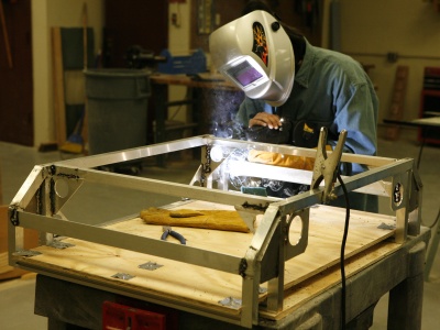
Chassis frame is MIG-welded Aluminum. Gussets were extensively utilized to stiffen and strengthen this very light frame.
View the welded frame drawings.
(2) forms were created to assist in accurately welding the frame.
Specifications
- Drive-train type: 6 wheel drive (Tank Drive) w/ alternative 7th Wheel 3 wheel drive pivot mode
- Motors: (1) CIM each side; (1) Globe driving 7th Wheel
- Gearbox: 24:1 reduction single-speed direct drive (½” keyed shaft)
- Transmission: Direct drive of Middle & 7th Wheels
- Slave Chain Drive for Front & Rear Wheels
- Type 35 Steel Chain & 22-tooth sprockets
- Rover Wheels (6” diam)
- Wheel-Base:Length: 20.25 in; Width: 33.25 in (to wheel centerlines)
- Max Speed: 5.9 ft/s


