DEWBOT II Mechanical
From DEW Robotics
DEWBOT II's scoring system is designed to:
- Score by shooting balls into the central high goal
- Alternatively score by schooting balls into the low side goals
- Collect balls off the playing field to reload the Shooter's storage hopper
Contents
Overview
Beater Bar
- A high-speed (ungeared Mabuchi RS-545SH2485 on a speed controller) front Beater Bar caught balls and drove them back to the Ball Lift. The Beater Bar also prevented balls from being lost during robot reverse drive. A pair of guides directed the balls into the Ball Lift entrance.
Ball Lift
- The Ball Lift is a vertical conveyor tower having a pair of conveyors: Left and Right.
- Each conveyor comprises:
- (5) 3/8" OD latex tube "cords"
- (7) conveyor rollers
- A Globe Motor direct drive of the bottom-most roller
- A spring tensioner on the top-most roller
- The two driven bottom-most rollers are angled 3° relative to the other rollers, providing a wider opening at the entrance of the Ball Lift thereby allowing easier ball entry.
- The two spring-loaded top-most rollers are separated further appart than the other rollers, loosening the conveyors grip on the balls as a deflector pushes the balls forward into the hopper.
- The right-side driven bottom-most roller is eccentric. This eccentric roller is at the level of the ball center while the balls are on the floor. The eccentric roller causes the conveyor to open to allow balls to easily enter and then to close to grip the balls tightly to lift them. The cycle time of the eccentric roller is the Globe Motor cycle time (0.74 s unloaded). Any balls only partially in the tower are pushed in by the underside of the "ski jump".
- Rollers are 2" diameter and grooved with (5) 3/8" diameter semicircular grooves to engage the latex tube "cords". Roller material is Nylon / Molybdenum disulfide composite. They are turned on a lathe.
- At the tower top, a deflector pushes the balls forward out of the tower and into the hopper. The increased roller spacing at the tower top facilitates this removal.
Hopper
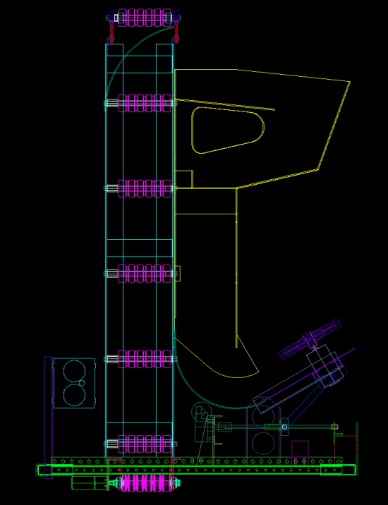
- A Polycarbonate 2-level Hopper was designed and build to store Balls and feed them to the Shooter. (Shown as Yellow in the CAD Diagram at top right)
- Originally designed and built 1.5 Balls wide with a capacity of 7 Balls, it was narrowed to 1 Ball width and a capacity of 5 Balls after the Philadelphia Regional to mitigate Ball jamming problems.
- Hopper floor slope was 5°.
- The Hopper was easily removable for service. Spare polycarbonate panels were included in our spare parts.
- The Hopper served as our primary sponsor display area.
Ball Chute - Feed Servos - "Ski Jump"
- Balls fed by gravity from the Hopper to the polycarbonate Ball Chute (also Yellow in the diagram top right). A pair of servo-driven stops controlled the feed to the shooter and kept that feed to one Ball at a time.
- At the bottom of the Ball Chute, a circular Aluminum guide (The Ski Jump - Teal in diagram) redirected the dropped Ball into the Shooter Wheels. A piano hinge connected the end of the ski jump to the back of the shooter table.
Shooter
- DEWBOT II used a double wheel shooter. KOP wheels were used, with each wheel directly driven by an ungeared CIM motor. The CIMs were driven by Victor speed controls. A Shooter Table constrained the Ball path at the Shooter bottom. High-speed photography was used to confirm that the Ball speed was (just) within the 12 m/s limits.
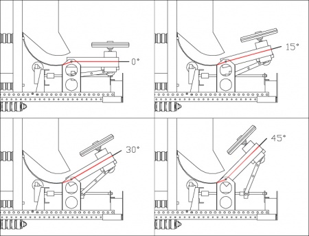
- Shooter elevation was variable between slightly < 0° and 45° via a screw drive. Limit switches prevented the elevation from exceeding these limits. The low end allowed us to score on low goals. Elevation needed to be 30° or higher for the high central goal. This was known from analysis (Al Koenig) and the "ski jump" was accordingly designed to work optimally at this elevation.
- Our plan was to use the vision system in an acquire mode to aim the robot and set the elevation (based on distance to target) before shooting. Alas, this system was never fast enough to be practical in competition, so manual dead reconning was employed in its place. Fortunately, 30° elevation provided the corrent shooter elevation for wide range of shooting positions.
- Without a traverse, we aimed the shooter by turning the robot. Without a working vision system, we aimed by dead reconning. This was slow. With a low shooter and a drive-train subject to deflection, opponents could and did block us.
- We discovered (mostly at Ramp Riot) that DEWBOT II could typically score 4/5 shots in autonomous mode. This was great! We were selected for playoffs (first time ever I think). We felt like Rock Stars. Alas, our opponents also discovered our capability and set one of their robots to knock us off course.
- Shooter wheels were guarded for safety. At Philadelphia, the guards were polyethylene colanders with appropriate cut-aways. These did not hold up well to competitive abuse and were therefore replaced with Aluminum guards. The Aluminum guards included a roof to constrain Ball path at the top.
Strengths
- Reliability (some jams)
- Flexibility to target either High or Low goals
- Easy ball collection
Weaknesses
- Low rate of fire
- Difficult and slow to aim
- Vision system aiming never worked well enough for competition
- Small hopper capacity
- Low Shooter position was easy for opponents to block
- Low scoring

