DEWBOT V Mechanical
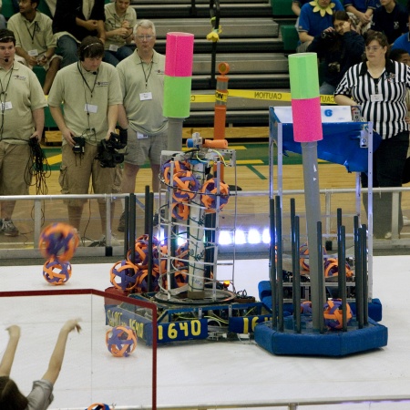
This section refers to the scoring part of the robot (whereas the drive-train refers to the "robot moving" part of the robot).
The scoring functions are:
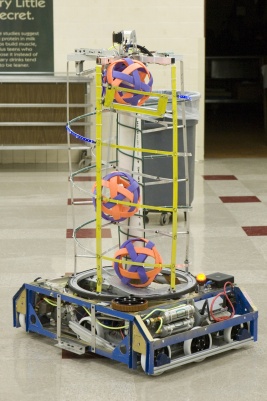
- Pick Moon Rocks (or Empty Cells or Super Cells) off the playing surface using a Beater Bar, which feeds up to a...
- Spiral Hopper. The Hopper has a central Spindle to drive the Moon rocks up to the...
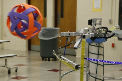
- Shooter. This shoots Moon Rocks up to about 5 ft into opponent's Trailers.
- The entire Hopper traverses about 270° to aim the Shooter (or to position the Hopper for pick-up)
- The Camera is fixed top-dead-center (tdc) on the Hopper top and aliged with the Shooter axis (accounting for parallax with the 5 ft shooting range)
- The intent was that the Camera would guide the Hopper traverse to facilitate aiming and scoring - this feature has not been used in competition yet
- Two strings of blue LEDs wrap around the top of the hopper. When a Moon Rock is in shooting position, a limit switch signals for the LEDs to light solid.
- When the vision system acquires an opposing target, the solid LEDs switch to flashing. The LED system provides the Driver & Opperator with a Heads Up indication of ready to shoot and target acquired.
- A Cry Wolf button is provided on the Operator Joystick to simulate target acquisition for opponants deception
- Dewbot V's strong and agile drive-train allows us to play agressively and to pin opposing robots
- We developed (3) strong Payload Specialists. Matt Klufas has a very high scoring rate from the standing positions. Alex Clark and Elizabeth Murphy both score very well from the sitting Outpost position.
- Dewvot V can collect and deliver Empty Cells to the Airlocks
- At Monty Madness a Dumper feature was added to the Shooter, which improved scoring
Contents
Beater Bar
A beater bar with curved back-plate is employed to pick up Moon Rocks.
The Beater bar is 20 in wide fabricated from 1” PVC pipe. A 1” OD x 1/16” aluminum tube inside the PVC provides rigidity and straightness. Two 1” wide wheel treads wrapped helically around the beater-bar’s exterior provide a high-friction surface to positively engage and catch the Moon Rocks.
The beater-bar is driven by a geared FisherPrice motor. This provides high torque at about 2 rev/s. Open the pdf format Beater Bar assembly drawings.
The robot chassis’ wide orientation allows a generous 19 in wide opening in the chassis front for Moon Rock entry, making Moon Rock collection easy. In Pick-up mode, the Pilot/Driver need only drive over Moon Rocks to collect them.
The Back-plate is curved at a 9 in radius and covers 68°. It is 20 in wide at bottom, tapering to 9 in wide at top. The back-plate is mounted so that curved surface is co-axial with the beater-bar, thereby maintaining constant compression on the Moon Rocks as they are lifted. Side-plates funnel Moon Rocks through a consistent opening into the bottom of the Spiral Hopper.
Back-plate and (2) side-plates are fabricated from thermally-formed 3/16” thick Tuffak® brand polycarbonate (donated by Arkema).
Beater Bar Development
Beater-bars are known technology to the Team, from 2006. The back-plate & side-plates are new for us.
The system was prototyped (using a flat back-plate) prior to design. Prototype testing provided the necessary degree of compression needed to reliably transport Moon Rocks.
Naturally, these dimensions together with the desire to make the Moon Rock opening in the front of the robot as wide as practical to make pick-up easier, had a significant impact on chassis and frame design. This had to be a early development.
(2) forms were created to accurately form the back and side-plates.
Beater Bar Specifications
- Device: Beater Bar & Back-Plate Moon Rock pick-up
- Motor: FisherPrice Motor with Gearbox
- Gearbox: 124:1 reduction
- Transmission: 1.5 in octagonal socket
- Capture Width: 19 in
- Control: Buttons 6 ("in") and 7 ("out") on the operator's joystick (Logitech 963291-0403)
Hopper
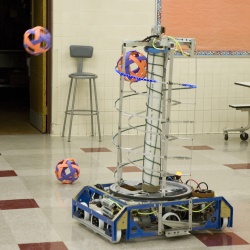
The Hopper & Spindle provide Moon Rock storage for the robot. They are integrated into the beater-bar and shooter systems.
The Hopper is a helical, up-flow magazine for Moon Rocks. The Spindle provides the necessary upward force to drive Moon Rocks to the Shooter.
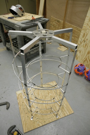
The Hopper mounts on the outer ring of a 23.6 in OD aluminum turntable (McMaster-Carr part 8233K14). This turntable allows the entire Hopper to traverse, like a turret, to aim the Shooter on top. The Hopper itself comprises a welded cylinder with (5) uprights and (2) helices: outer and inner. The outer helix, welded directly to the uprights, contains the Moon Rocks within the Hopper and provides the necessary compression (against the Spindle) to allow the Moon Rocks to be driven upwards. The inner helix, welded to stand-offs to the uprights, supports the Moon Rocks. The Pitch of both helices is 10 in. Each helix is (3) turns tall. The top of the Hopper is closed with a 5-arm, pop-riveted “Spider”. The bottom of the Hopper has a formed polycarbonate ramp to facilitate transfer of Moon Rocks onto the helix.
The open spiral design allows easy loading and unloading of Moon Rocks at the start and end of each match.
The Spindle is a 4 in PVC pipe with 2 courses of polycord on the exterior to drive the Moon Rocks. The outer course of polycord is in a spiral perpendicular to the inner helix, thereby providing force in the Hopper spiral’s direction. The Spindle possesses a 1 in x 1/16” wall internal aluminum tube, which is driven at the bottom. Wood plugs connect the aluminum tube to the PVC pipe top and bottom.
The Spindle is driven by a Nisso-Denso motor via a chain drive at 22:12 step-up gearing providing a no-load Spindle speed of 2.6 rev/s and a stall torque of 4.3 ft lbf. Chain drive includes a tensioner. There are (2) 1 in bearing races at the bottom and a ball-bearing turntable at the top of the Spindle.
In competition, the Nisso-Denso driven spindle operation was found to be inadequate. On 30-May-2009, it was replaced with a Bainbots RS-545 motor with a 64:1 P60K planetary gearbox. This drives the Spindle via a chain drive using 15:12 step-up sprockets providing a no-load Spindle speed of 5.1 rev/s and 9.9 ft lbf stall torque.
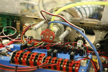
A Traverse Drive rotates the Hopper over 270° in order to aim the shooted. Open the pdf format Traverse Drive drawings. A Vex potentiometer is attached to the bottom of the hopper's CPVC central Conduit, and this potentiometer provides hopper traverse angle information.
All Hopper and Shooter wires, Camera cables and a pneumatic supply line run through the Conduit. The Conduit's dual purposes are: 1) protect these wires & pneumatic line; and 2) provide a Hopper traverse angle reference for the potentiometer.
Hopper Development
The spiral Hopper concept was inspired by Team 694’s 2006 design, featured in Wilczynski & Slezycki, “FIRST Robots, Behind the Design”, Rockport (2007).
The Hopper and Spindle was prototyped and tested. Spindle design started as brushes (ala 694’s) but evolved with testing to the solid pipe with frictive exterior (the polycord).
While a solid cylinder was used to prototype, the decision was made to use a welded, open spiral for the final design. This decision was based primarily on weight (the hopper as-built is only about 7 lb) and secondarily on ease of manually loading and unloading Moon Rocks.
(6) forms, mandrels or jigs were created facilitate construction of the Hopper – more than half of the total used by the team in 2009.
Hopper Specifications
- Device: Spiral Hopper & Drive Spindle
- Motor: Nisso-Denso replaced by Bainbots RS-545
- Gearbox: Integral worm gear replaced by Bainbots 64:1 P60 3-stage planetary gearbox
- Transmission: Type 35 steel chain w/ tensioner; 22-tooth drive and 12-tooth driven sprockets; 22-tooth drive replaced by 15-tooth
- Capacity: 14 Moon Rocks
- Traverse Control: stick of the operator's joystick (Logitech 963291-0403)
- Spindle Control: Buttons 4 ("down") and 5 ("up") on the operator's joystick (Logitech 963291-0403)
Shooter
The Shooter/Dumper device is located at the upper end of the hopper's spiral track. The Shooter device is a third-class lever (fulcrum - effort/piston - load/Moon Rock) driven by a pneumatic cylinder, which increases the launch speed of the Moon Rock. The Shooter is capable of launching Moon Rocks up to five feet and can shoot several times per second. It is normally operated with the Spindle running "up".
A dumping function was added at the 2009 Monty Madness Competition (Skillman, NJ, May 16) by running a strip of velcro from the last outer upright of the hopper to the inside of the spiral, across the shooter and disconnecting the timing belt that actuated the Gate with the shooter (see Development). Later, a small ramp was welded onto the hopper just inside the opening to better guide the Moon Rocks out of the hopper when the Spindle is left "up". This function dumps several Moon Rocks per second into an adjacent opposing trailer, while leaving the shooting function uninhibited.
Shooter Development
The team prototyped several dispensing mechanisms, including upper, lower, and tandem shooting wheels, beater-bars, and multiple lever designs as well as direct-shooting pneumatic cylinders. The design team selected the third-class pneumatic lever for its range, speed, and short reload time.
After mechanical advantage calculations and basic design, the team was able to prototype the design on-the-fly and finish final fabricated soon afterward.
After experimenting with several ramps, the team also decided to construct a Gate to contain the Moon Rocks in the hopper until they're ready to be fired. This gate was actuated along with the shooter via a timing belt bolted to the bottom of the lever arm. The Gate was also spring-loaded (with equilibrium position down). It also served to alter the launch angle and subsequent range of the Moon Rocks(if the trigger was held only briefly, the gate could not descend entirely, creating a steeper ramp). The Gate was later disconnected when the dumping function was added.
The dumping function was considered throughout the competition season, and the final design was an on-the-spot an invention at the post-season Monty Madness Competition (May 16, 2009).
