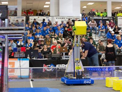
DEWBOT XIV Lift
- Ability to score via scale, switch and exchange
- Ability to score in "lost" scale on 2nd level (defines scoring height)
- Ability to rotate arm to back to score in autonomous without having to turn around
- Lift time from pick-up to scale scoring ~ 1 sec
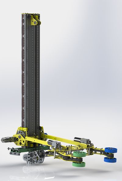
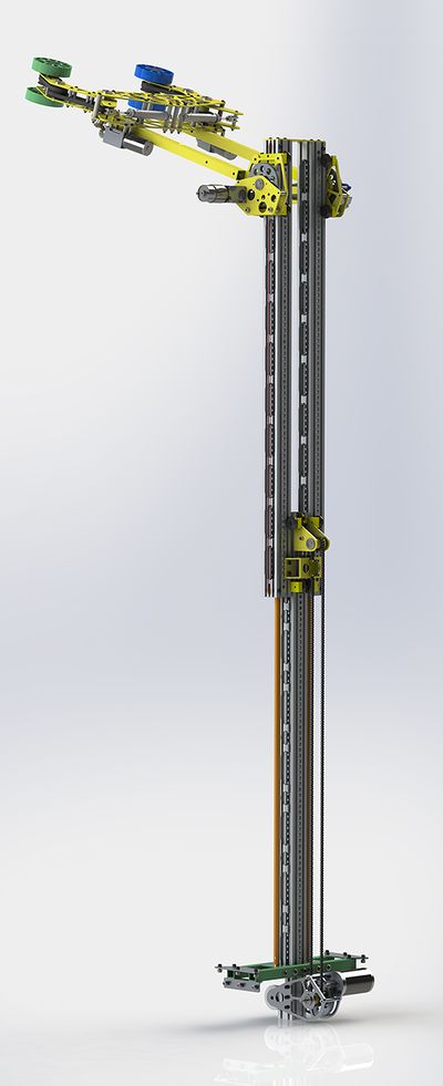
The lift is a 2-stage, single center post, cascade design. The main structural elements (stage 0 & 1) comprise 80/20 2020 profiles with 80/20 2752 roller wheel brackets. The 2nd stage comprises a carriage with arm drive, arms and roller claw.
The objective of scoring from either the front or rear of the robot (to facilitate autonomous scoring) drove the selection of a center post approach. The arm is able to rotate above the top of the lift when the lift is raised and allows the robot to score in the scale from the robot's rear. Earlier concepts employed a conventional frame lift with the thought that the claw could translate within this frame, but calculations revealed that passing the claw through a frame that fits on the short axis of the robot was impractical.Contents
Center Post Lift
Typical lifts employ two fixed posts (left and right - stage 0) with a moving frame (stage 1) between these. A carriage (stage 2) can ride within this frame to provide double lift.A center post design inverts this model. A single fixed post provides the foundation for the lift (stage 0). A compact frame (stage 1) is driven up and down on this center post. A carriage (stage 2) rides outside the compact frame. The result is a very compact lift, allowing arm & claw rotation outside and over the lift for scale scoring to the front and back of the robot.
Key advantages of this inverted, or "inside-out" design are:
- The design enables arm & claw rotation over the lift top and toward the robot back for back scoring
- By keeping the lift compact, left-to-right, racking and jamming is more easily avoided
- The design allows high reach and careful and flexible placement of Power Cubes
- The design manages Center-of-Gravity very effectively - DEWBOT XIV is visibly more stable than other effective lift-scale robots
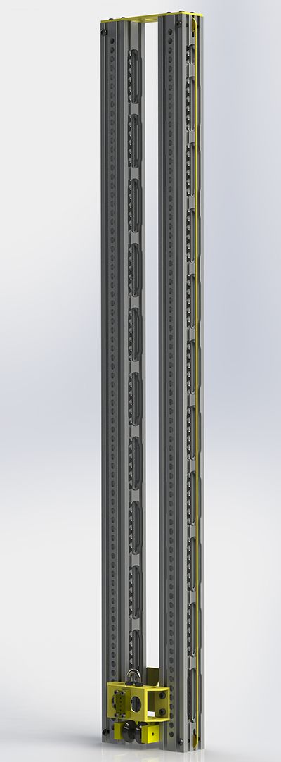
The center post and stage 1 frame elements are 80/20 2020 (2" x 2") profiles. These profiles are extensively relieved to reduce weight and manage center-of-mass. High center-of-mass is an occupational hazard for scale-capable Power-Up robots.
80/20 2752 roller brackets with custom rollers allow the lift elements to move relative to each other. Custom rollers resolve a binding issue created by the stock rollers.
Flexible Mount
The base of the Center Post is secured to the carbon-fiber / birch electronics panel, which was re-enforced with extra layers of carbon fiber for this purpose. 3.5" above the electronics panels, the Center Post is sandwiched between two 1" x 1" x 1/8" fiberglass pultrusions. These pultrusions are secured to the robot chassis frame at the pultrusions' ends. Fiberglass pultrusions are used in lieu of aluminum members because of the flexibility provided by the fiberglass.
Sab-BOT-age has used fiberglass pultrusion in applications requiring both high tensile strength, high elasticity and low brittleness since 2011. It is critical to fill hollow pultrusion elements in areas where bolts pass through the pultrusion, otherwise the pultrusion can be crushed and fail.
Lift Drive
A single-stage gearbox drives a #25 chain loop, driving the lift's first stage. Originally, a single CIM motor drove the lift via a 6:1 reduction (12t:72t spur gears) with an 18t sprocket driving the chain loop. An encoder on the gearbox's output shaft allowed accurate determination of the lift height.Before Westtown the lift drive was modified by replacing the single CIM with dual 775Pro motors mounted to a 7:1 single-stage Versaplanetary gearbox. The spur gearbox was changed to us 14t & 70t gears (5:1 reduction), providing 35:1 overall reduction. The 18t output sprocket remained as before. The dual 775Pro lift drive was used for all competitions through FRC Championship.
The 2nd lift stage (the carriage), is raised via a cascade system. The cascade drive loop comprises two lengths 1/8" diameter synthetic rope (left and right) with ends tied to the top and bottom of the carriage. Each cascade drove loop is anchored to the top of a fiberglass rod itself anchored to stage 0 and located centrally within each of the stage 1 2020 profiles. 3-D printed guides maintain the central positioning of these fiberglass rods within the 2020 profiles. 1" OD x 1/8" round belt brass pulleys (McMaster-Carr 6447K500) are located at the top and bottoms of the 2020 profiles to guide the cascade drive loop.
Constant Force Spring
Vulcan Constant-Force springs were employed on the lift to support the lift's mass so that motors would not need to hold this mass up.In its first iteration, a single 1.5" wide, 25 lbf spring was used. This ran inside the lift's center (Stage 0) post with its end connected to a string guided by a pulley at this post's top and connected to the (Stage 1) Chain Anchor. The bottom mounted on a spool at the posts's base, using the back end of the lift gearbox. As this spring took up most of the width of the post's central cavity, it was prone to jamming. This would jam the lift. The first iteration was used at Westtown.
The second iteration replaced the internal 25 lbf spring with an external 2" wide 30 lbf spring mounted on the post's front face. The upper lift chain sprocket mount was redesigned to accommodate at spool, while the spring's end was connected directly to the (Stage 1) Chain Anchor. This provided additional counterbalance for the lift's mass and completely eliminated the spring jamming issue. The second iteration was used from Seneca through FIRST Mid-Atlantic Championship. This was a clear improvement.
The third iteration retained the external 2" wide 30 lbf spring mounted on the post's front face and added a 16 lbf spring internally within the center post (mounted as the original 25 lbf spring had been mounted).
Lift Stage 1
The lift 1st stage is made up of two (2) 44.8" lengths of heavily-relieved 2020 profile. These profiles are securely connected at top and bottom. The 2020 profiles include mounts top and bottom for pulleys which guide the cascade drive rope.At the bottom of the stage, a pair of 80/20 2752 roller brackets whose rollers engage the center post grooves.
Lift Stage 2 - Arm Carriage
The lift's 2nd stage is the carriage which supports and controls the articulation of the arm and attached intake claw. This section will describe the actions and design of the carriage and arm. The actions and design of the intake claw itself is covered in a separate page.
Key requirements and actions of the Arm Carriage are:
- Support arm and intake claw (with Power Cube)
- Drive arm rotation from -5° to 162°
- Measure arm angle
- Lock arm position at several pre-determined angles
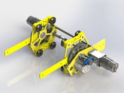
Arms are 1" fiberglass pultrusion which attach to intake claw. They are supported by 1/8" 6061 Al plates (redesigned 7075 Al plates after FRC Championship) to 84t arm drive gears. One 84t arm drive gear is on each side of the carriage. These 84t arm drive gears are each driven by a 30t gear; the pair of 30t gears are mounted on a common 3/8" hex drive shaft. The common 3/8" drive shaft is driven by a pair of 775Pro motors with 100:1 (2 x 10:1) Versaplanetary Gearboxes. Overall gear reduction for the arm drive is (10 x 10 x 84/30 = ) 280:1.
- Pneumatic Cylinder for Detent Brake
- Detent holes in 84t arm drive gear
- Angle sensor
- Mounting point for cable tray
The Pneumatic cylinder is a 1" bore x 0.5" stroke flexible mount cylinder (McMaster-Carr 62245K153), having a 0.472" diam 304 stainless steel rod and M5 air connections. It was originally planned to use this in a friction brake, but the moment arm was too great for this to hold. As an alternative, (3) 0.5" detent holes were drilled into the left 84t arm drive gear at 1-3/8" from the gear center and in positions to hold the Intake Arm at 45°, 71° and 130° above forward-horizontal. The 71° position is the starting point, as it holds the intake claw securely, entirely within the robot perimeter. 45° is used for normal transport. The 130° position is used for scoring on the scale to the rear of the robot during autonomous. When extended, the 0.472" cylinder rod engages the 0.50" detent holes, locking arm rotation.
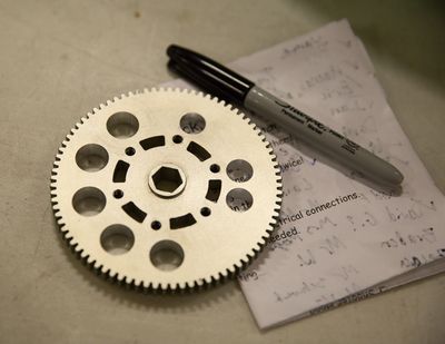
The 84t arm drive gears also possess 0.625" holes for lightweighting. The Right side gear has (10) such holes, evenly positioned. The Left side gear has (5) such holes, as these holes cannot be placed in the pneumatic cylinders arc or engagement.
The angle sensor and its mount were identical to those used on the Swerve Modules.
