DEWBOT IV Control
Operator Interface
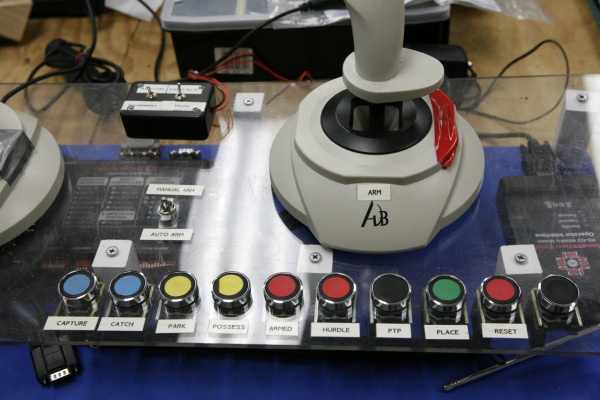
The operator interface consisted of three joysticks, 10 push buttons and 1 switch. Two joysticks were used for "tank drive" steering, the third was used for manual arm placement. The switch was used to toggle between the manual joystick and the use of the push buttons.
The ten push buttons corresponded to actions on the robot: Capture, Catch, Park, Possess, Armed, Hurdle, Prepare To Place (PTP), Place and Reset. The buttons were color coded and were in a left to right order that would normally be used in game play. (The unlabeled black button was used in the development of the software and as a "just in case" button).
Software
The programming for tank drive was fairly clear and is something that prior robots had.
The fork-lift-catapult was controlled by a state machine. A limit switch on the robot sensed the lowest position of the fork-lift. There was a shaft encoder attached to the lifting drum that gave the position of the lift in the carriage. There was limit switch at the top to keep the carriage from coming off the rails.
When the operator pressed the reset button, the carriage would travel downwards until the lower limit switch. This was "ZERO" position. The software would then lift the carriage slightly and put the forks in the Capture position (about 5 ticks up).
As the operator pressed the buttons the software would move the carriage up or down using a PID algorithm to stop in the correct location. The state machine control also served as a safety, the catapult could not move into an armed position unless the carriage was in the proper location. Likewise, "Hurdle" would not trigger the catapult unless the current state was "Armed" and the system was ready.
A refinement was made late in the season that "Capture" would also do the reset process. This took care of position errors that would creep in due to the cable tension changing during an event.
A VEX sonar sensor was placed on the base looking forward through the forks. When it sensed the ball (and it was in the "Capture" state, it would trigger the "Catch" state, grabbing the ball. This worked about half the time in game play, it would miss if the front of a fork moved the ball before it was triggered.
Autonomous Mode
Autonomous Mode was a combination of using a gyro for direction and a shaft encoder attached to a VEX wheel for distance. The software kept the robot going in the right direction via a PID algorithm. Once the correct distance was reached the robot would turn left and continue.
A combination of issues with traction of the base and the way the encoder was attached the wheel made the system unreliable. After the season ended we rebuilt the distance wheel and were able to get four lines to work 4 times out of 5 trials.
Control System Files
DEWBOT_IV_RC_and_OI_Connections.pdf - connection document for DEWBOT IV
DEWBOT IV Control Software - This a link to the primary code in text format.
DEWBOT IV code.zip - full collection of code and documents
See our other robots at FRC Team 1640
