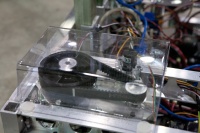
Difference between revisions of "DEWBOT VII Drive Train"
MaiKangWei (talk | contribs) |
MaiKangWei (talk | contribs) (→Drive Transmission) |
||
| Line 56: | Line 56: | ||
==Drive Transmission== | ==Drive Transmission== | ||
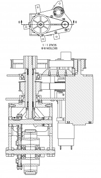
| − | [[image:2011_drive-train_cs.jpg|200px|right|thumb| | + | [[image:2011_drive-train_cs.jpg|200px|right|thumb|Cross-Section through drive-train module]]Each wheel is independently driven, with each drive design being identical. A CIM motor provides the drive power to each wheel via the following drive-train: |
:# The CIM drives an 18T HTD5 synchronous belt pulley on its shaft | :# The CIM drives an 18T HTD5 synchronous belt pulley on its shaft | ||
:# driving the 420mm HTD5 ''Pivot Drive Belt'' | :# driving the 420mm HTD5 ''Pivot Drive Belt'' | ||
Revision as of 11:31, 13 March 2011
January 10th 2011: The big debate of the night The Drive Train. Pivot vs. Tank (6W)Probably one of the most important decision to make for the robot. There were many pros and cons for both sides. Do you continue with the drive train you used last year, with the increased knowledge on how to build, program and drive it, and the added agility that come with but lose the 8 motors it takes and the amount of processor resources it will eat up?
Or...
Do you go with a simpler design, with can be created quickly, anyone can drive, uses less motors and processor, and can leave more time for working other aspects of the robot. However with this, sacrifice the maneuverability of the other option. While everyones input was listened to, the two main groups that needed to answer this were our drivers and our programmers.
The winner: Pivot, Our programmers and drivers were confident in their skills it may seem as a higher risk but will definitely yield a higher reward. Driver & Co-Captain Carly was adament: "This is a key competitive advantage for the team, and we've already made the investment to develop it!". We decided to go with what was our most valuable asset last year, agility. We were the fastest most agile Bot out there. This season is certainly shaping up to be a challenging one indeed.
Contents
Pivot developments since the 2010 season
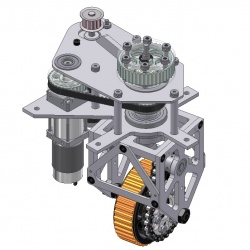
- The joint between the pivot top and pivot tube failed on two occassions. This needs to be made more reliable.
- The time required to change a pivot if it fails is too long. This needs to be reduced to 5 minutes.
- Setscrews loosen, and as a result the transfer axle tended to drift. A redesign is needed to prevent drift without reliance on set screws.
- Weight reduction.
On 22-Nov, the team ran a Value Engineering session on the 2010 Pivot Drive design, which included a "Straw Man" proposal for a modular Pivot Unit. With a modular Pivot Unit, pivot replacement during a competition would entail module replacement, with the module including the drive and steering motors and the angle sensor.
Based on the feedback received on the "Straw Man", an improved "Wooden Man" (pdf) design was developed to elicit further critique. This "Wooden Man" design provided the starting point for the 2011 pivot drive design.
Strengthening the Pivot Top / Pivot Tube Joint
The 2010 pivot design utilized a tight fit between the hole in the pivot top and the inserted pivot tube. The insertion depth was 3/8". the joint was epoxied and three 8-32 set screws were threaded into the joint at 120° intervals to strengthen the joint and prevent rotation. (6) such pivots were produces in 2010 (4 for use and 2 spares). Two failed in service (during off-season competitions). Pivots which failed in this way could not be repaired.The 2011 pivot addresses this deficiency by:
- The insertion depth is is increased to 1/2".
- A thermal interference fit between the pivot top hole and pivot tube is employed. The hole is undersized by 0.0025". Prior to assembly, the pivot tops are heated to 450°F to expand the hole enough to allow the tube to fit. Assembly must be done quickly! Thermal fit calculations for the Pivot Tube/Pivot Top assembly are provided.
Torture testing shows the new joints to be very strong (we haven't been able to break them).
Modular Design to cut replacement time
If a 2010 pivot needed to be replaced with a spare, the process required no less than 30 minutes. On the two (off-season) occassions when pivots failed in our busy 2010 season, this meant that Sab-BOT-age missed a match each time; letting down alliance partners. This is unacceptable.
In addition to having more reliable pivots in 2011, a key objective was to reduce pivot change time to 5 min maximum, thereby avoiding missed matches. We achieved this goal.
We achieved it by making the pivot a module which includes the Pivot, CIM drive motor, steering motor & gearbox, angle sensor and the transmission connecting these components. The pivot module can be replaced by removing (5) bolts and (5) electrical connections; then reversing the procedure.
There are Left & Right modules. A robot has (2) of each. All left modules are identical and interchangable, as are all right modules. Identical includes angle calibration.
Steering
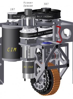
Banebots RS-540 motors with Banebots 256:1 reduction 4-stage planetary gearboxes were selected for steering. The gearbox's ½" shaft drives a 32-tooth HTD5 synchonous belt pulley and is also hard coupled to the Pivot's angle sensor (as with last year's pivot, the steering motor shaft angle is used as a surrogate for the pivot angle). The 1" OD pivot tube has a driven 32-tooth HTD5 synchronous belt pulley. A 360mm HTD5 x 15mm wide belt connects the drive and driven 32T steering pulleys (1:1).
Angle sensor & calibration
Mentor Gary Deaver selected Vishay 981HE0B4WA1F16 absolute encoders in lieu of last year's Cherry AN8 encoders due to better accuracy and lower cost ($28 v. $38 ea.). Good call.
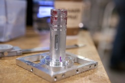
Vishay sensors have ¼" "D"-shafts which are hard-coupled with the steering gearbox shafts. Polycarbonate mounting rings were machined which have #8-32 thr'd mounting holes at 20° intervals over a full circle. As the Vishay sensor mounting slots have +/-10° adjustment slots, these mounts allow full mechanical calibration of the sensors. All sensors were calibrated identically, thereby allowing easy Pivot Module replacement.
Solving Transfer Axle Drift
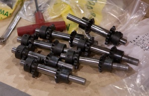
The Transfer Axle's job is to transfer rotational power from the Coaxial Drive Shaft to a #35 chain driving the robot's wheels. The Transfer Axle mounts a 16T Miter Gear, which is driven by an identical Miter Gear on the Coaxial Drive Shaft, and a 9T #35 chain sprocket. A thrust bearing taked the axial load from the miter gear, while flanged ball bearing races bear the shaft's radial loads.In 2010, this axle was a simple keyed 3/8" steel shaft. Keys in the Miter Gear and Sprocket maintained rotational alignment. Set screws in the Moter Gear & Sprocket were intended to maintain axial conformance. The problem developed that the set screws allowed slippage and that the Trasfer Axles thereby drifted axially. When (not if) an axle drifted out of its terminal ball bearing race: the axle failed; drive ceased; miter gear teeth were damaged; and repair required >5 minutes (time not always available).
The 2011 solution is a ½" Transfer Axle, turned down to 3/8" on both ends and keyed in the appropriate places for the Miter Gear and 9T #35 Sprocket. The "fat" axle center prevents axial drift, even without set screws.
Drive Transmission
Each wheel is independently driven, with each drive design being identical. A CIM motor provides the drive power to each wheel via the following drive-train:- The CIM drives an 18T HTD5 synchronous belt pulley on its shaft
- driving the 420mm HTD5 Pivot Drive Belt
- which drives the 56T HTD5 sychronous Pivot Drive Pulley
- which turns the Coaxial Drive Shaft from its top
- turning a 16T Drive Miter Gear at its bottom
- which drives the 16T Transfer Axle Miter Gear
- thereby turning the Transfer Axle
- and the 9T #35 Transfer Axle Sprocket
- driving the Wheel Drive Chain
- which drives the Wheel via the attached 24T Wheel Drive Sprocket
There is no formal Gearbox. All reduction is accomplished using belts, pulleys, chains and sprockets (the Miter Gears are 1:1). Noise is reduced this year due to the synchonous belt replacing the #35 chain from the CIM to Pivot. Overall reducion is (56/18)x(24/9) = 8.30. Maximum robot speed is 9.8 ft/s.
The belt is HTD5 x 15mm. The chain is Type 35 steel. Belt and chain lengths are kept to a practical minimum.
The wheels are 4" AndyMark Plaction Wheels with roughtop treads. Gary Deaver's Tread Mounting System was employed from the start.
Mass
Pivot module mass is 9.1 lbm, excluding the belt guard. This is a reduction of 0.9 lbm per unit vis-à-vis the 2010 equivalent (and in spite of a heavier steering motor/gearbox).
Belt guard
For safety, all pivot modules are fitted with a belt guard. This guard is formed fron 1/16" thk polycarbonate and secured to the chassis frame via mushroom-head fasteners.Wheelbase
- width: 20.75 in
- length: 30.75 in
Chassis
Chassis is TIG-welded 6061 Aluminum with 27" x 37" outside dimensions. Main elements are 2 x 1 x 0.130 U-channel and 1 x 1 x 0.125" Square, with 1/8" plate used for gussets. Mass of the chasses weldment is 14.1 lbm.
The chassis was welded using side and front/back templates. Chassis elements have alignment holes to assure proper positioning on the templates. The four chassis sides were welded first, on the templates. These were next squared, clamped and welded together for form the complete structure.
Bumper attachment points are designed into the chassis weldment.
