DEWBOT VI Drive Train
- Its superior maneuverability. This should be especially valuable in aligning with soccer balls and with the goal.
- Safety while crossing the bump. A 6-wheeled drive (6wd) robot would tilt over further during the climb and would also experience two tipping points. The second of these (coming off the flat top of the bump) will put the robot at a considerable tipping risk unless center of mass (CoM) is very low.
DEWBOT VI is able to safely cross the bump and also drive through the tunnel. For both of these actions, the robot will need to drive in its long (x) axis direction. Chassis orientation is important for us in BREAKAWAY. The robot will not be capable of driving along the top of the bump.
Pivots
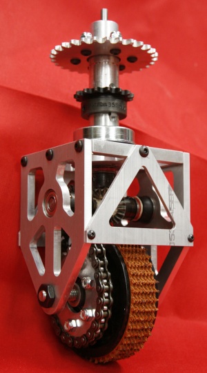
Pivots are co-axially driven and can be rotated infinitely. All (4) pivots are identical.
At the start of build season, a prototype pivot was built using the design developed for the hypothetical 4-wheel pivot drive-train. Following prototype testing, a number of modifications were made in the design of the pivot assembly prior to machining parts for DEWBOT VI's pivots. Rather more substantive changes had to be made to the pivot mounting plates due to necessary changes to the motor positions.
The pivot pivots on a 1" pivot tube, within which runs a coaxial drive shaft. Roller bearings at the top and bottom of the pivot tube bear the drive shaft's radial loads. The coaxial drive shaft terminates with a 16T-16 diametrical pitch Miter Gear. A thrust bearing bears the axial loads developed by the miter gear. The pivot tube pivots within bottom and top pivot plates secured to the chassis frame using (2) 1" ball bearing races and (1) 1½" ID thrust bearing. The top pivot plate also serves as motor mount for the drive and steering motors.
The coaxial miter gear drives an identical miter gear on the horizontal transfer shaft. A 9T drive sprockat also mounted on the transfer shaft drives the wheel via a type 35 chain. The transfer shaft uses (1) thrust bearing (to bear the miter gear axial load) and (2) 3/8" ball bearing races.
View a drawing of the pivot assembly, including the cross-section.
Wheels are AndyMark 4" Plaction Wheels with Roughtop tread.
Pivot bodies are machined 6061 aluminum. Machining was graciously provided by Wamac, Inc., a Downingtown Area Robotics sponsor.
Drive
Each wheel is independently driven, with each drive design being identical. A CIM motor provides the drive power to each wheel via the following drive-train:- The CIM drives a 9T Type 35 sprocket on its shaft
- driving the Pivot Drive Chain
- which drives the 28T Pivot Drive Sprocket
- which turns the Coaxial Drive Shaft from its top
- turning a 16T Drive Miter Gear at its bottom
- which drives the 16T Transfer Shaft Miter Gear
- thereby turning the Transfer Shaft
- and the 9T Transfer Shaft Sprocket
- driving the Wheel Drive Chain
- which drives the Wheel via the attached 24T Wheel Drive Sprocket
There is no Gearbox. All reduction is accomplished using chains and sprockets (the Miter Gears are 1:1). This makes an unusual noise. Overall reducion is (28/9)x(24/9) = 8.30. Maximum robot speed is 9.8 ft/s.
All chains are Type 35 steel. Chain lengths are kept to a practical minimum.
Unlike tank drives, all CIM motors drive in the same direction, so there is no left-to-right mismatch between motors' clockwise and counterclockwise performances.
Steering
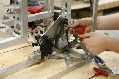
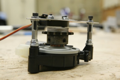
Window Motors are used to drive the Pivot steering. One motor per wheel. A 15T (3/4" bore) drive sprocket is attached to the output hub of each Window Motor and that 15T drive sprocket is adapted as follows:- (2) 4-40 tapped holes are made in the sprocket face
- a 3-layer polycarbonate magnet holder is made with a magnetic encoder magnet secured in the middle 1/8" thk layer
- magnet and polycarbonate holder are secured via (2) 4-40 FHCSs
A Cherry AN8 series magnetic rotary position sensor is mounted about 2mm from the face of the magnet holder.
The Window Motors drive the Pivots via type 35 chain and a 15T (1" bore) driven sprocket on the Pivot Tube. Since Drive and driven sprockets have the same tooth count, measuring the drive sprocket angle provides a good surrogate for measuring the pivot angle.
Chassis
Wheelbase is 28” (x) x 21.5” (y). CoM is 9” above grade and centered between the four wheels.
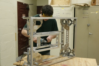
Chassis frame is welded aluminum. Pivot mount plates are riveted to the frame using steel rivets with steel back-up washers. Attention was paid to providing adequate structural support to the pivot mounts and to the kicker supports while still keeping mass as low as practical. In addition, corner posts are extended down to provide protection to the pivots.Bumper mounting points are designed into the frame gussetts. These bumper mount points are at the bumper zone elevation midline (13" elevation).
Control Strategies
A multi-mode control approach will be employed. Supported control modes are:
- Absolute Crab (with twist)
- Relative Crab
- Target-tracking Crab
- Biaxial Snake
- Automobile


