DEWBOT VI Mechanical

- DEWBOT VI’s scoring strategy is focused on scoring soccer balls. Towards this, we should be able to:
- Herd up to 3 soccer balls and push these into the goal if playing in the alliance zone
- Herd balls with the robot side as well and also push into the goal using the side.
- Kick the ball towards the goal. We expect to be able to reliably score from Mid-field and to at least be able to reliably move balls from the opposing zone to the alliance zone with a single kick over both bumps. Bonus if we can reliably score from the opposing zone.
- Clear soccer balls from the tunnels
- DEWBOT VI has no provisions to Elevate or Suspend.
- Our initial attempt to actively possess balls failed. As a result, ball possession and centering at Finger Lakes was entirely passive. This approach was not very useful and was corrected at Philadelphia with an improved, active possessor.
Contents
Kicker
- How do you move a soccer ball?
- How do you get a soccer ball you can't pick up into a goal?
- It's not a big surprise we ended up with a kicker on DEWBOT VI.
- The Kicker is latex-tubing powered. Kicker is 15” wide and had a kicking face tangent to the ball at the contact point.
- The Kicker will be cocked and fired pneumatically via the following sequence:
- Disarmed - Kicker in untensioned condition, such as after being fired
- Cock - a Main 2” bore, 4” stroke Cocking Cylinder with a 1.25" bore "helper" Cylinder extend to drive the Cocking Arm which in turn drives the Kicker into the fully-tensioned position. The Cocking Arm and Kicker pivot on the same axis.
- Latch - a ¾” bore, ½” stroke Latch Cylinder extends to close the Kicker Latch, holding the Kicker in the tensioned position
- Arm - The Cocking cylinders retract (only the "helper" cylinder is powered on the retraction, to conserve on air), retracting the Cocking Arm at the same time. The Kicker remains in the tensioned position due to the Latch.
- Fire - the Latch Cylinder retracts, opening the Latch and releasing the energy stored in the latex springs.
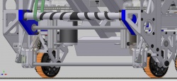
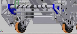
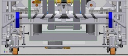
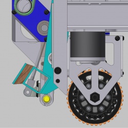
This sequence is illustrated in the following four (4) images. In these images, the Kicker is color-coded Cyan, the Cocking Arm is color-coded Olive; and the Latch is color-coded Violet.
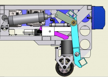
1 & 5) Kicker disarmed or fired
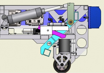
2) Kicker cocked
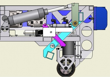
3) Kicker latched
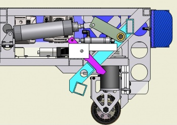
4) Kicker armed


- The Kicker power will not be adjustable during a match. It will be possible to adjust the latex tubing between matches to attenuate the Kicker’s power.
- The Kicker is a robust, welded aluminum assembly supported by a substantive welded structure within the chassis. Firing the Kicker releases a great deal of stored energy.
The Kicker must be disarmed prior to crossing the bump.
Kicker Development
- Kicker development proceeded in stages:
- Conceptual testing of several different kicker concepts using relatively simple prototypes to demonstrate feasibility.
- Refinement and testing of the selected concept - a latex-tube powered, swinging, wide kicker.
- Design and construction of intended Kicker and the design and construction of a proxy chassis into which the Kicker was installed. Kicker performance was verified. Cocking and Latching systems developed and tested. A Possessor tested. When we were satisfied with the Kicker System's overall performance, the System was transferred to the Robot.

- Concepts tested were:
- A motorized flywheel driven Kicker
- An air-spring Kicker based on a constrained, charged, 2" bore pneumatic cylinder. We really wanted this to work. It would have made our engineering jobs easier & happier.
- A latex-spring powered Kicker - the selected concept. It's just awesome, and awesome trumps easy any day. 'nuff said.
- Kicking cross-field (over both bumps) required (5) pre-tensioned latex bands. The 2" bore Cocking Cylinder had some difficulty tensioning this, so we added a "helper" Cylinder. First a 3/4" bore; then 1.25". A bonus of the "helper" Cylinder is that it can do the retraction by itself, thereby conserving compressed air.
- The Latch proved the most troublesome element to develop. High pressure on the latch contact surfaces either prevented release or resulted in unacceptably high wear rates. Steel was always used for these parts, but ultimately a piece of hardened tool steel was used for the catch plate. A couple of wire ties on the Latch provided a lubricous Latch surface which could be easily maintained.
Possessor
- The possessor went through a great deal of evolution and development.

Mk I
- The first version of Possessor consisted of a 15" x 1¼" PVC pipe covered with grippy 1/16 neoprene rubber sheet shore 40 hardness. The roller was direct-driven by a Fisher Price motor attached to a Banes Bot 256:1, and later a 64:1 planetary gearbox. The latter gearbox provided an unloaded rotational velocity of about 4 revolutions/sec. This seemed to be effective on the static proxy chassis, but when mounted on the robot, it became clear that the possessor allowed the robot to ride up over the ball far too easily and was ineffective at possessing the ball. This original possessor was removed and replaced with a passive system just prior to shipping.

Mk II
- The Team's experience at the Finger Lakes Regional, however, convinced us of the value of an effective possessor. We therefore resolved to revisit the concept. It was clear that both ball possession and centering was key for accurate and rapid scoring. It would allow us to spend less time lining up the robot to the ball and to the goal, and make it so we just have to align the robot + the ball to the goal.
- The problem of possessors pulling balls under the chassis was a common one at Finger Lakes. The main diet of robots seemed to be #5 soccer balls. We set to develop a possessor which would not eat soccer balls.
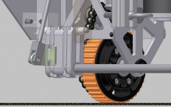
- The possessor system we developed utilizes dual rollers:
- A powered possessor roller which captures the ball. This is positioned as far forward on the frame as possible and contacts the ball near its top. This possessor roller is full robot width and belt-driven. We dropped a stage from the Bainbots gearbox (still using the FisherPrice motor) for an unloaded rotational speed of 19 rev/s. The possessor is a 1" OD Al tube. Drive belts are a pair of welded polycord belts (14-7/8").
- An unpowered back roller is located behind and below the possessor and serves as a back-stop for the ball. Should the possessor begin to eat the soccer ball, the back roller causes it to break contact with the ball. The back roller is a freely-rotating 1/2" aluminum rod (changed to a steel rod at Drexel).
- The possessor tube is covered with a double helix of hard polycord and soft latex rubber tubing. Each helix has a pitch of 2". The polycord seems to be more effective at centering, while the latex is grippier and makes the possessor more effective at possessing.


- Both rollers are full robot width, making it easier for the driver to catch the soccer balls.
- The possessor may be reversed to facilitate pushing balls into the goal.
- The improved possessor was developed entirely using Autodesk Inventor and the Proxy Chassis. Building the proxy chassis was certainly one of the best decisions we made during the 2010 build season.
- The performance of the improved possessor at Philadelphia played a role in our overall good performance a this regional competition (although this role was secondary to the improvements made in the drive control software). DEWBOT VI's possessor performance at Philadelphia was good (and a huge improvement over Finger Lakes), but definitely not at the top of the class.
Mk III
At PARC, Monty Madness and (BR)2, we were dissatisfied with our possessor's performance. While it seemed to perform well at the STEM Defined demonstration, in the heat of competition, it tends to either fail to possess the ball, or to cause the robot to drive over the ball.
We've observed that robots with effective possessors often have passive rollers at or below the ball centerpoint. Installing such a low roller on DEWBOT VI without a major redesign is not trivial. Key challenges are:
- Avoiding interference with the kicker
- Avoiding interference with the pivots
- Maintaining our ability to cross bumps without difficulty. A low-position roller intrinsically is in the way when climbing a bump
But not impossible. An articulated, low, 3rd possessor roller has been designed for the existing robot.
- The roller articulates up and out of the way for bump crossing.
- Two 3/4" diameter x 4" stroke pneumatic cylinders provide the actuation. Both run from a single solenoid. Restrictor valves will need to be installed on the solenoid vents.
- A hard stop is provided for the possessor in the lowered, working position (the design does not rely on the pneumatic cylinders to provide this stop).
- While rotating between the deployed and retracted states, the low possessor assembly does not break the frame perimeter.
- It is proposed that the low possessor will automatically retract when the operator relaxes the kicker to cross a bump; and automatically deploy when the kicker is armed; normal kicking will not change the possessor state.
- In addition, it is likely that the combination of reversing the driven possessor and retracting the lower possessor roller would be a useful, low-velocity means to positively eject balls into the goal from the goal's ramp (without having too drive the robot entirely into the goal).
View the detailed drawings.
View of possessor with bottom roller in working (deployed) position
Detail of bottom roller articulation mechanism
View of possessor with bottom roller raised (retracted) for crossing bumps
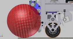
Side elevation with parts made invisible showing position of ball relative to the possessor elements
Front elevation
Robot view
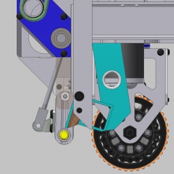
Kicker close approach to 3rd roller - 1/3 - kicker boot
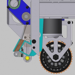
Kicker close approach to 3rd roller - 2/3 - closest approach
Kicker close approach to 3rd roller - 3/3 - maximum extension


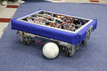
Sideguards
- A quick test revealed that DEWBOT VI easily drove over balls when driving towards then sideways. This would result in a penalty.
- Eyebolts and bungee sideguards were added to the robot side to prevent incursion of the balls under the frame. These sideguards do not interfere with crossing the bump. They do enable the robot to herd balls into the goal using the long chassis side.
Crossing bump with sideguards in-place - no problem
Herding with robot side & sideguards. We can no longer drive over the balls from the sides.


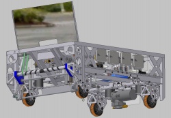
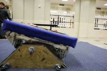
Mirror
A 12" x 24" polycarbonate Mirror was installed on the top front of DEWBOT VI between Monty Madness and (BR)2 to enable our driver to see balls hidden behind the bumps while strafing. DEWBOT VI's drive-train is uniquely suited to this tactic.
The mirror is hinged to fold down when going through the tunnel. Mirror stays down when pushed down (so maybe having a servo to raise it would be a good idea). When the mirror was first mounted, the latex spring seemed a cheesy, temporary expedience. In retrospect, it is a highly-effective, elegant, minimalist mechanism.
When deployed, the mirror is angled forward at 12°. This provides the driver with a clear view of the back side of the bump in either the Mid or Opposing Fields.
Debuted at (BR)2, the mirror works. We could see hidden balls behind bumps (although with 18-20 balls on the field, finding balls was not such a high priority at (BR)2). We can get through the tunnel without trouble and even went through backwards (with the mirror already down).
The mirror was cited (along with our multi-mode Pivot drive-train) by the judges when awarding us with the (BR)2 Engineering Excellence Award.