Difference between revisions of "DEWBOT XII Drive-Train"
MaiKangWei (talk | contribs) (→Design) |
MaiKangWei (talk | contribs) (→Design Considerations) |
||
| Line 43: | Line 43: | ||
Due to concern that a high-traction track would make steering difficult and leave the robot subject to T-bone attack, one of the belt surfaces selected for testing was the medium-traction, abrasion-resistant T-cover surface. Following testing, this medium-traction belt was selected for the robot. The belt/T-cover combination has a minimum pulley diameter of 80mm. To prevent the edge of the belt from digging into the field carpet, the belt edges were milled to a 45<sup>o</sup> miter. | Due to concern that a high-traction track would make steering difficult and leave the robot subject to T-bone attack, one of the belt surfaces selected for testing was the medium-traction, abrasion-resistant T-cover surface. Following testing, this medium-traction belt was selected for the robot. The belt/T-cover combination has a minimum pulley diameter of 80mm. To prevent the edge of the belt from digging into the field carpet, the belt edges were milled to a 45<sup>o</sup> miter. | ||
| − | A 30-tooth drive pulley was selected based on the belt's 80mm minimum pulley diameter. The pitch diameter of the 30-tooth pulley is (30 teeth x 10mm pitch / π = ) 95.5mm (3.76 in). From the standpoint of speed and gear reduction calculation, the pitch diameter is effectively the wheel diameter. | + | A 30-tooth drive pulley was selected based on the belt's 80mm minimum pulley diameter. The pitch diameter of the 30-tooth pulley is (30 teeth x 10mm pitch / π =) 95.5mm (3.76 in). From the standpoint of speed and gear reduction calculation, the pitch diameter is effectively the wheel diameter. |
To climb a 4-5/8" step, the front pulley/idler must be mounted above and in front of the first road wheel, so that the belt forms an angle enabling the climb. A 45<sup>o</sup> angle was used and, because we wanted to cross obstacles bidirectionally, this was applied symmetrically to the drive-train's front and back. | To climb a 4-5/8" step, the front pulley/idler must be mounted above and in front of the first road wheel, so that the belt forms an angle enabling the climb. A 45<sup>o</sup> angle was used and, because we wanted to cross obstacles bidirectionally, this was applied symmetrically to the drive-train's front and back. | ||
Revision as of 23:41, 30 March 2016
After six years of successful Swerve Drive development, along comes FIRST Stronghold. Our first conclusion concerning the game: it's not a swerve game. The outerworks obstacles require a different approach.
Three approaches were explored:
- 6 or 8 wheel tank drive using 8" (or larger) pneumatic wheels;
- 6-wheel tank drive with a bogie suspension
- treaded tank drive
Of these, the first and last were tested; the bogie suspension was not tested because it seemed to be more suited to low velocity travel than high.
An 8-wheel tank chassis was built using 8" AndyMark pneumatic wheels. All wheels were driven. This chassis was able to cross b & d obstacles, but bounced excessively in the process. The crossings were not under control. The moat crossing was especially troublesome.
Treaded tank drive was able to cross all type b & d obstacles while retaining good control. An attribute of tracked vehicles is that they have better mobility than pneumatic tires over rough terrain. They smooth out the bumps, glide over small obstacles and are capable of crossing breaks in the terrain. This is why military tanks use treads.
Contents
Drive-train Objectives
- Facilitate reliable and rapid crossing all b & d type outerworks obstacles in either autonomous or teleop control;
- Non-interference with crossing types a & c outerworks obstacles;
- Speed consistent with game needs (~12 ft/s) while retaining fine control
- Turns quickly and easily - without requiring excessive motor power or creating large hysteresis;
- Not sensitive to T-bone attack
- Reliable & easily serviceable
Drivetrain Specifications
- ~12 ft/s maximum speed
- Able to climb 4-5/8" steel steps
- A minimum of 3in ground clearance between tracks to avoid fouling on Ramparts or Rough Terrain
- Bi-directional: crosses type b & d obstacles (approximately) equally well driving either forwards or backwards
- Modular drive-train enabling rapid replacement
Design Inspiration
Sam Shawe-Owner-President of Outback Mfg (63076 Crusher Ave, Bend Or 97701 - www.outbackmfg.com - sam@outbackmfg.com) had designed FRC chasses around Brecoflex belts and pulleys for previous years' FRC games. Posted video of these chasses demonstrated that they managed FIRST Stronghold defenses well. Sam Shawe graciously shared these CAD designs with us.
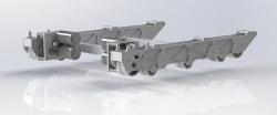
Early Shawe design
Later (developed) Shawe design


Sam Shawe's designs provided inspiration and a starting point, but we designed DEWBOT XII's tracked drive system from our objectives and specifications.
Design Considerations
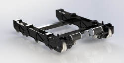
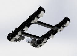
As with the Shawe chasses, DEWBOT XII's drive-train is based on a pair of Brecoflex 50mm wide TK10K13 steel-belted polyurethane timing belts. This belt design possesses a central raised guide which prevents belt shift left-right. This guide indexes into grooves in the drive-train pulleys and idlers. This belt has a 10mm pitch and may be ordered in any length at 10mm increments. Brecoflex provides FRC teams with a design guide.
Due to concern that a high-traction track would make steering difficult and leave the robot subject to T-bone attack, one of the belt surfaces selected for testing was the medium-traction, abrasion-resistant T-cover surface. Following testing, this medium-traction belt was selected for the robot. The belt/T-cover combination has a minimum pulley diameter of 80mm. To prevent the edge of the belt from digging into the field carpet, the belt edges were milled to a 45o miter.
A 30-tooth drive pulley was selected based on the belt's 80mm minimum pulley diameter. The pitch diameter of the 30-tooth pulley is (30 teeth x 10mm pitch / π =) 95.5mm (3.76 in). From the standpoint of speed and gear reduction calculation, the pitch diameter is effectively the wheel diameter.
To climb a 4-5/8" step, the front pulley/idler must be mounted above and in front of the first road wheel, so that the belt forms an angle enabling the climb. A 45o angle was used and, because we wanted to cross obstacles bidirectionally, this was applied symmetrically to the drive-train's front and back.
A 33.75 x
15.0