DEWBOT XVIII Arm
Due to the long reach required to score (especially CONEs) on the Top ROW, CHARGED UP seems to be a classic Arm Game. Nice change, but Sab-BOT-age has built only four Arm Robots to-date. These were:
DEWBOT I - Triple Play - 2005
DEWBOT III - Rack 'n Roll - 2007
DEWBOT VII - Logomotion - 2011
DEWBOT XIV - Power Up - 2018


The centerline of the Top ROW CONE NODEs are 3' 3-3/4" from the GRID front. Add 3-1/2" for bumpers and 2-1/2" for the radius of our rotating paddles and you are just shy of 3' 10" when the paddle centerline is directly above the Top ROW CONE NODE centerline. Maximum extension is 4' beyond the frame perimeter. This requires either a 2-axis Arm or a 1-axis Arm combined with a directionally extending lift. Sab-BOT-age picked the 2-axis Arm without extension.
Contents
Language
We defined the following Tetrapod-themed terms in talking about the Arm:
- Shoulder - The rotational axis on the Chassis. The Shoulder is driven by the Shoulder Gearbox
- Humerus - The Arm section extending from the Shoulder, terminating at the:
- Elbow - The 2nd rotational axis, used to articulate the:
- Radius & Ulna - A pair of structural elements terminating with the Monkey Claw
The Elbow is driven by the Elbow Gearbox. There is no Wrist.
Structural
The Shoulder mount comprises a pair of 1/4" 6061 Al Shoulder Mount plates each with a (1/2" Hex flange) bearing which together support the Shoulder Axle. These Shoulder Mount plates are securely bolted to a 2" x 1/8" wall square tube running longitudinally along the chassis's axis.
The Humerus is fabricated from 2" x 1/8" wall fiberglass pultrusion. The ends of the pultrusion are filled with carbon fiber/epoxy.
The Radius and Ulna are 1" x 1/8" wall fiberglass pultrusion. As with the Humerus, the ends are filled with carbon fiber/epoxy.
Shoulder and Elbow axles are both 1/2" Hex 7075 T6 Al (VexPro).
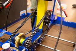
Both axes are driven by a pair of chains (left & right). Driven sprockets are bolted directly through filled portions of the pultrusions and also to hex hubs which engage both ends of the axles.
Arm Drives
Shoulder and Elbow gearboxes are similar. Both are:
- powered by a pair of NEO motors
- 1st reduction 4.67:1 via Spur Gears - 14T steel pinions driving 56T 7075 Al 20 DP - 14.5° Pressure Angle
- 2nd reduction 30:1 via Worm Gearset - single start 1144 steel worm driving 30T Bronze worm gear 12 DP - 14.5° Pressure Angle
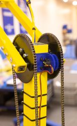
- Dual chain sprocket output for final reduction stage (via chain & sprocket) - 3rd reduction stage differs between the two gearboxes
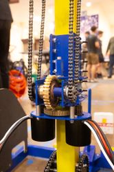
- The Shoulder Gearbox uses #35 chain and 4:1 reduction for a final 560:1 reduction (12T driving 48T)
- The Elbow Gearbox uses #25 chain and 3.56 reduction for a final 498:1 reduction (18T driving 64T)
The use of a worm gearset prevents back-drive of the arm. To allow powered-down arm movement, the worm shaft is extended beyond the gearbox and fitted with a hex. A ratchet wrench can drive the shaft.
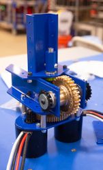
The Shoulder Gearbox is securely mounted to the central 2 x 2" beam (the same beam supporting the Shoulder Mount).
The Elbow Gearbox is securely mounted to the lower part of the Humerus.
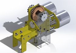
Shoulder Gearbox (CAD)
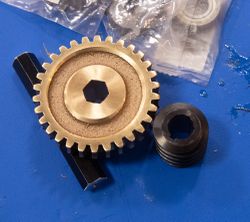
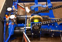
Worm Gear & Worm
Elbow Gearbox
Elbow Gearbox
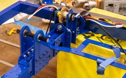
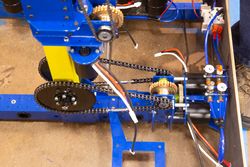
Chassis with Shoulder Mount & Gearbox
Elbow Gearbox
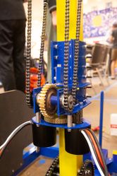
Elbow Gearbox
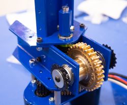
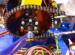
Shoulder Drive
Shoulder Drive
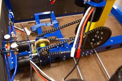
Shoulder Drive
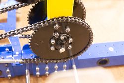
Shoulder Drive
Shoulder Drive


Control
Shoulder and Elbow axes are both fitted with Absolute Encoders for angle measurement and limit switches to prevent damage. The are is intended to run mostly on presets for different operations, although manual operation is also available. In the video below-right, for each action, the shoulder rotates for 0.8 s, the elbow rotates for 2.2 s. Time is identical in both directions.
Elbow Encoder
Shoulder Encoder
Arm Tests

