Difference between revisions of "DEWBOT X Drive Train"
MaiKangWei (talk | contribs) |
MaiKangWei (talk | contribs) |
||
| Line 1: | Line 1: | ||
| − | of | + | Due to the very strong expected defensive nature of Aeriel Assist, and serious bandwidth limitations on our design team, we made the decision on 5-January to utilize [[DEWBOT IX Drive Train | DEWBOT IX's Drive Train design]] (which has been published) with a couple important upgrades. |
==Issues with the 2013 pivot design== | ==Issues with the 2013 pivot design== | ||
| Line 7: | Line 7: | ||
:# One Pivot tube/Pivot Top weld failed in 2013 (in off-season competition), resulting in the total constructive loss of the pivot module. This failure rate is considered acceptable at this time | :# One Pivot tube/Pivot Top weld failed in 2013 (in off-season competition), resulting in the total constructive loss of the pivot module. This failure rate is considered acceptable at this time | ||
:# One Igus bushing came loose from the module top plate. Repaired. | :# One Igus bushing came loose from the module top plate. Repaired. | ||
| − | :# Occasional loss of calibration was were | + | :# Occasional loss of calibration was experienced due to slippage of the angle sensors' fiberglass flex couplings' set screws. |
| + | :# Driving straight during autonomous was not possible without at least two (catecorner) pivots equipped with tachometers - 2013 pivots were tachometer-ready, but only tachometer-equipped for development trials. | ||
| + | |||
| + | ==Developments on the 2013 pivot design== | ||
| + | |||
| + | Development of the 2014 pivot design was really the development of sensors and software necessary to enable the robot to drive straight in autonomous. [[User:Gdeaver | Gary Deaver] led the sensor development while Patrick D led software development. | ||
| + | |||
| + | The following design changes were made: | ||
| + | :* | ||
| + | |||
| + | |||
==Value Engineering== | ==Value Engineering== | ||
| Line 14: | Line 24: | ||
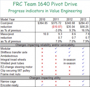
Each Autumn, we conduct a value engineering exercise on our pivot drive design to understand what changes we would make if we were to select pivot drive again. The results of this exercise are summarized in the accompanying Table. | Each Autumn, we conduct a value engineering exercise on our pivot drive design to understand what changes we would make if we were to select pivot drive again. The results of this exercise are summarized in the accompanying Table. | ||
| − | |||
| − | |||
| − | |||
| − | |||
| − | |||
| − | |||
| − | |||
| − | |||
| − | |||
| − | |||
| − | |||
| − | |||
| − | |||
| − | |||
| − | |||
| − | |||
| − | |||
| − | |||
| − | |||
| − | |||
| − | |||
==Pivot Module [[media:Swerve_1640_2013.zip | CAD Design]] and [[media:Swerve_BoM_2013.xls | Bill of Materials]]== | ==Pivot Module [[media:Swerve_1640_2013.zip | CAD Design]] and [[media:Swerve_BoM_2013.xls | Bill of Materials]]== | ||
Revision as of 14:33, 11 March 2014
Due to the very strong expected defensive nature of Aeriel Assist, and serious bandwidth limitations on our design team, we made the decision on 5-January to utilize DEWBOT IX's Drive Train design (which has been published) with a couple important upgrades.
Contents
Issues with the 2013 pivot design
Our 2013 robot, DEWBOT IX, participated in more competitions, demos and driver practice than any robot before it (we said this last year, but it is true again this year). That said, the 2013 pivots performed extremely well, but the following issues were observed:
- One Pivot tube/Pivot Top weld failed in 2013 (in off-season competition), resulting in the total constructive loss of the pivot module. This failure rate is considered acceptable at this time
- One Igus bushing came loose from the module top plate. Repaired.
- Occasional loss of calibration was experienced due to slippage of the angle sensors' fiberglass flex couplings' set screws.
- Driving straight during autonomous was not possible without at least two (catecorner) pivots equipped with tachometers - 2013 pivots were tachometer-ready, but only tachometer-equipped for development trials.
Developments on the 2013 pivot design
Development of the 2014 pivot design was really the development of sensors and software necessary to enable the robot to drive straight in autonomous. [[User:Gdeaver | Gary Deaver] led the sensor development while Patrick D led software development.
The following design changes were made:
Value Engineering
Value engineering seeks to widen the gap between the value a product provides to the customer and its cost. Value and cost in this context includes both monetary and non-monetary measures. For example, addressing the issues listed above increases the value of the product to the customer (drive team & pit crew). Cost includes monetary cost (measured following FRC cost guidelines) but also mass, manpower and machine time.Each Autumn, we conduct a value engineering exercise on our pivot drive design to understand what changes we would make if we were to select pivot drive again. The results of this exercise are summarized in the accompanying Table.
Pivot Module CAD Design and Bill of Materials
Calibration - no change from last year's
Chassis & Wheel-base
Chassis was once again welded 6061 Al. Mostly 1" x 2" x 0.130" U-Channel.
Wheelbase is 21" (nominally wide) x 22.25" (nominally long). Chassis exterior dimensions are 27.75" x 27.75".
