DEWBOT X Shooting
Contents
Specifications
- SAFETY: The stored energy intrinsic to this game makes it very easy and tempting to design a robot capable in inflicting serious injury. DEWBOT X accidents should not be capable of breaking bones or causing serious crushing injuries
- Score in High Goal Reliably (and on the move)
- Truss shots - to Human Players or alliance robots
- Pass to other robots - superceded by Roller Frame passing
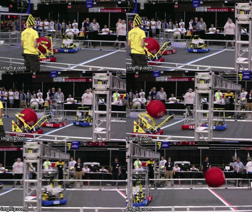
The drive team's shooting focus was on scoring via high-trajectory, short distance shots, prefferably in contact with the low goal. There was also a clear desire for a lower-trajectory, longer scoring shot. Scoring from the white zone was nice-to-have for autonomous, but not considered essential.
Approaches Evaluated
A number of approaches to shooting were considered, including a catapult, slingshot, roller-claw with spring-loaded punch and a direct pneumatic punch. All but the roller claw advanced to prototype testing. A direct pneumatic firing catapult entered the field as a late contender and was also prototyped.
Direct pneumatic punch did not provide the speed needed and was abandoned.
Successful catapult and slingshot prototypes were built and tested. Both utilized latex tubing as springs. the catapult had the advantage of being able to make significantly longer shots than the slingshot. Scoring from the white zone appeared to be possible with the catapult, but not with the slingshot.
The decision was made for the Slingshot on 13-January based on two factors:
- Safety - For several reasons, the slingshot approach is intrinsicly safer than the catapult and significantly reduces the potential for injury
- Tactics - Focus on scoring from short distance; truss shots and catchable passing favors the high-trajectory, lower-velocity shooting demonstrated by the slingshot. While the catapult is likely to be capable of delivering these shots as well, this had not been demonstrated at the decision time. A drawback is that these high-trajectory, low-velocity shots are necessarily short-distance. DEWBOT X will need to move in autonomous before shooting. A somewhat frightening proposition.
The decision for the Slingshot places the requirement on control & programming for straight driving during autonomous.
Slingshot
From the first concept, the slingshot consisted of a pair of elastic latex tubing loops crossing at approximately 90. A 2" PVC pipe and pipe cap assembly covered the elastic crossover point and served as a ball punch and attachment point for the retraction mechanism.
Elastics were 1/2" OD x 1/8" ID natural latex.
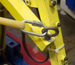
Elastics were strung corner-to-corner across a substantially square shooter frame, mounted on eyebolts at the frame corners. Originally the elastics passed directly through the eyebolts, but were later secured to the eyebolts using threaded chain connectors, thereby facilitating servicing.
About 100 lbf is required to pull back the elastics into firing position.
Winch vs Pneumatic retraction
The sling shot needs to be tensioned and released. These are generally two separate actions requiring (generally) different mechanisms. Early slingshot testing utilized manual retraction and release. After further prototypre development, retraction was accomplished with a 1½" bore 10" stroke pneumatic cylinderand later with a 2" bore 8" stroke cylinder driving a lever (to effectively increase the stroke).
Robot design efforts were challenged to find space to mount the required retration cylinder. A 1½" bore 10" stroke pancake cylinder was specified and priced which could in principle have fit, but this significantly raised the CG and was difficult to keep in the frame perimeter while avoiding interference with the ball. It was also an expensive cylinder. Prototype pneumatic release remained manual and a satisfactory release mechanism was never designed.
Key issues with the cylinder approach were:- Space to fit the cylinder
- How to reliably release (and reliably reconnect if connection was lost with release
- With a single cylinder, pull-back distance was limited to a fixed distance (although precision regulators were in fact purchased to test a pressure-limited variable pull back system; pull-back variability due to cylinder friction made this impractical)
An alternative tensioning and release mechanism is a winch. Calculations indicated that a CIM motor driving a 1" radius winch could pull back the elastics with a 10:1 or higher gearbox.
Once tensioned a winch could be held by either dynamically by the CIM or via a ratchet.
Winch release could be accomplished either by releasing a dog gear or similar mechanism (especially in the case of a dynamically held winch) or by first releasing a dog gear or similar mechanism and then releasing a ratchet (in the case of a ratchet-held winch). The dynamic system would require constant power to the CIM whenever it was tensioned, whereas with the ratcheting system, CIM power could be cut once the correct tensioning was achieved.
A winch offered the opportunity of using a load cell to dynamically control tensioning. This in turn would allow software adjustment of the tensioning and therefore the shot. This controllability was seen as a useful feature for game tactics.
While a winch was compact and therefore avoided a cylinder's space issues; and the release design seemed more manageable, it had it own issues:
- Our pneumatically-tensioned prototype released by disconnecting the elastics from the tensioning mechanism; therefore there were no inertial or frictional penalties imposed on shooting by the tensioning system. A winch would necessarily impose inertial and frictional losses on shooting.
- For dynamic tensioning, the CIM must always be powered; it can get hot; it can be affected by voltage variations.
- The dog gear mechanism of AndyMark's shifter gearbox (which we utilized with modification) was never designed for the loads it would experience in this service.
Winch
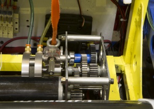
The team had experience with design of a single CIM shifting gearbox for DEWBOT V. This gearbox utilized parts from an AndyMark Shifter gearbox, but had an additional reduction step which took the gearbox to 24:1 reduction overall in low gear. Since the team had retained the spare gearbox, we had a ready prototype in hand for testing. This tesing demonstrated that:- the dog gear release (with the two rapidly spinning axles) does not impose unacceptable inertial and frictional losses on the shooter;
- the dynamic tensioning (using the CIM to hold the elastics in shooting position without a rachet) was feasible; and
- the 3/4" bore pneumatic actuator originally used for the AndyMark Shifter was inadequate to actuate the dog under the high loads imposed by the winch system - a 1-1/2" bore actuator was needed to overcome the loads and release reliably.
Based on these tests, the decision was made to use a winch for tensioning and release.
A new gearbox was designed and built for the winch. It retained the 24:1 reduction and AndyMark Shifter parts, but with some critical changes:
- The small dog gear was removed
- A 1/2" 7075 Al Hex shaft was used for the winch output shaft with a 45T Al gear (am-2035) and winch drum made from AndyMark hubs (am-0096a) - Al used to reduce angular momentum
- Dog gear latching surfaces were beveled
- A Bimba 1-1/2" bore 1/2" stroke pancake cylinder was employed for latching/release actuation
- The entire gearbox pivots on a shaft located bottom-center. The winch strap pulls the back part of the winch up as the elastics are tensioned; forcing the front part of the winch gearbox down onto a 100 lbf load cell.
- The CIM is controlled to provide a set-point load measurement on the load cell.
- An eye-bolt guides the winch strap, assuring on-drum winding.
Shooter Frame
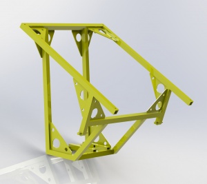
The shooter frame is a weldment securing the elastics and the winch and holding these in correct relation to each other. The main structural elements are 1" x 1/8" wall 6061 Al square tubing with 1/8" 6061 Al gussets. Short lengths of 1/2" diameter 6061 Al rod provide pivot points for securing the shooter frame to the to the chassis weldment at the robot's front, while angle pieces serve as pneumatic clevis mounts for securing the shooter frame to the chassis weldment at the robot's rear.The winch is mounted so that the winch strap pulls back the center of the elastics along a line which is perpendicular to the plane of the untensioned elastics.
Both cutting and welding required great accuracy. All shooter frame part ends were milled, to assure accurate lengths and angles. There are a large number of non-right-angle welds on the structure and welding set-up to assure angular accuracy was painstaking. Fortunately, the team's welding shop has both the tools and the skill to provide such intricate weldments with very efficient workflow.
Trajectory
Two ball trajectories can be used, based on the position of the 3" stroke cylinders at the back of the shooter frame. The high trajectory shot (cylinders retracted) has an initial elevation of 68 deg. The low trajectory elevation is 57 deg. Most shots used low trajectory.
