DEWBOT VIII Ball Collection and Storage

- Quickly and reliably pick balls off the playing field
- Ability to top load at the Inbound Station
- Able to possess three balls
- Able to prevent possession of more than three balls
- Fast transport of balls to the shooter
Ulitmately, this system took the form of:
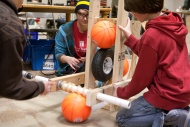
- A 19" wide beater bar on the wide front side of the robot; pulling balls in and keeping them there;
- An alternative top hopper feed; mechanism still works but hopper has degraded over time due to non-use;
- A funnel to guide balls from the 19" beater bar to the narrow lift entrance;
- A lift entrance, comprising: a) a driven Lift Wheel; b) a static pinch bar; and c) a flexible scoop; and
- An angled lift, having a posterior lift belt and two anterior lift rails; (4) IR sensors register ball positions within the lift assembly; the lift is capable of storing (3) balls and tracking the number of balls stored; the lift top communicates directly with the shooter.
Contents
Key Technical Challenges
- The strategic decision to cross the barrier together with the drive-train decision to use Pivot Drive again leads to the practical requirement to keep all rigid ball lift mechanisms above 4.5" above grade (at least while crossing the barrier).
- The strategic decision to enable 3-robot bridge balancing led to the decision to be able to drive the robot in the wide orientation (the desire to also drive in the long orientation to facilitate barrier crossing influenced the Pivot drive-train decision). This was seen to enable ball collection due to the wider ball entry orifice, but...
- ...Funneling down the balls collected with a 19" Beater Bar to a discrete ball lift in the short distance allowed by a wide chassis orientation while avoiding rigid elements lower than 4.5" is a clear challenge.
- Loading the lift should be automated and not require direct human control.
- We want to top load and floor load. Is this one mechanism or two?
- 1640 tradition is to build scoring mechanisms and particularly pick-ups, lifts and shooters which are too slow for champion robots. We sought to change this.
The Barrier Crossing and Drive-train decisions (which were not bad decisions) are clearly expensive. Ball Collection and Lift was where this cost was to be paid.
Concepts
Some key concepts considered were:
- The wide orientation collection was seen to be an obvious benefit (but, in retrospect, I wish more though was given to this and the funneling of balls from a wide collector to a narrow lift).
- Ball pick-up & lift was inspired strongly by Team 293's 2006 (Aim High) robot1. The model mechanism was not actually a ball pick-up mechanism, but a lift only. This mechanism comprised a pair of large-diameter (approx 10 in) pneumatic wheels driving balls within an S-shaped guide to a shooter.
- A pinch bar at an elevation no lower than 4.5 in, together with a lower lift wheel also no lower than this elevation, could pinch a ball between them to lift it off the ground without having any rigid portion below 4.5 in elevation (thereby clearing the barrier). The pinch bar and lift wheel may be counter-rotating or alternatively the pinch bar may be non-rotating.
- A Geneva Wheel could take the place of 293's top pneumatic wheel, thereby providing clear indexing.
- The bottom lift wheel could feed a linear belt-driven, guide rail constrained lift directly
- Non-contact IR sensors could provide ball indication at critical positions.
- Such indication could automatically control the lift; and
- Such indication could also prevent possession of more than three balls by reversing the beater bar.
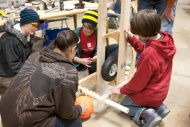
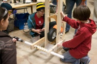
Prototypes
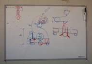
Concept sketches
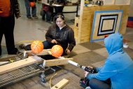
Beater bar prototype test
Lift wheel prototype
Pinch Bar (driven)
Pinch bar test
Geneva wheel
Geneva wheel
Lift pulley
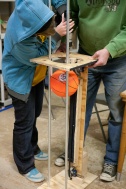
Lift prototype assembly
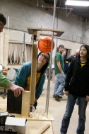
Lift test


Design details
Ball Path

Beater Bar
- A beater bar tangential to the robot chassis. This is driven by the same motor as drives the barrier wheels. The beater bar is a 2.26" OD formed Kevlar composite tube with 6mm polyurethane round-belt rings around the exterior to provide grip. 6mm polyurethane round belts also serve as drive transmission. The barrier wheel unloaded transmission speed is 2.28 rev/s, but pulleys speed this up to x.xx rev/s for the beater bar.
Funnel
- The Funnel directs balls captured by the wide beater bar down to the discrete Lift Wheel. These are bent steel rods with loose polybutylene piping (red - see photo at right) over. The polybutylene piping rotates to prevent pinch points and thereby resist over-riding balls.

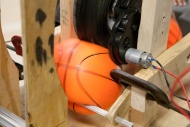
Lift Wheel
- A driven 8" AndyMark pneumatic wheel (AM-0970) compresses incoming balls against a pinch bar and scoop, picking them off the floor and loading the balls into the lift.
- The wheel is driven by an AndyMark AM-0912 motor coupled to a BaneBots P60 64:1 reduction gearbox. This drives the wheel at an unloaded speed of 4.2 rev/s (wheel circumferential speed of 105 in/s). Stall force on the wheel circumference is 60 lbf.
Pinch Bar
- The Pinch Bar provides a pinch point for lifting balls with the lift wheel. In the original prototype, the pinch bar was driven in counter-rotation to the lift wheel. During later testing, it was found that this counter-rotation was not necessary. The pinch bar is a part of the chassis frame weldment.
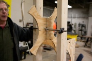
Scoop
- Competition experience taught us that the pinch bar can easily over-ride balls when the robot is at speed. To improve ball pick-up reliability and speed, we added a shovel-shaped scoop to direct balls up into the lift. The scoop is 1/16" polycarbonate and is shaped and designed to bend upwards and out of the way when crossing the barrier.
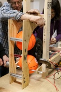
Lift
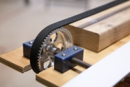
- The lift stores up to three balls in preparation for shooting. Balls are raised by a 25mm wide 2m HTD5 synchronous belt in the posterior position of the lift which is driven by a 56T pulley in turn driven by an AndyMark AM-0912 motor coupled to a BaneBots P60 64:1 reduction gearbox. This drives the pulley at an unloaded speed of 4.2 rev/s providing an unloaded belt speed of 46 in/s. Belt stall force is 138 lbf. An idler pulley is positioned at the top of the lift belt run.

- Two ½" (nominal) galvanized steel conduit tubes make up the lift rails constraining the balls against the lift belt.
- Four IR sensors are mounted to monitor ball positions within the lift.
Control Strategy
Beater Bar/Barrier Wheel and Lift Wheel drives normally operate continuously. The Lift Belt runs discontinuously. All three (3) of these motors are controlled by Victors and are in one of three states: off, full forward & full reverse power.
The Beater Bar/Barrier Wheel, Lift Wheel and Lift Belt can all be reversed to eject balls from DEWBOT VIII's Lift into an ally's pick-up if desired; this may be done in either hybrid or teleoperated play.
All of these drives offer manual control, if needed.
Beater Bar/Barrier Wheel
- When the robot drive train is in barrier crossing mode (skinny snake), this drive is controlled by the needs of the barrier wheels. They will run either full power forward or full power reverse to match the direction of pivot drive.
- At all other times, this drive is controlled by the Beater Bar needs. Normally this runs full power inwards, but reverses if the controller determines that the robot is in possession of three (3) balls.
Lift Wheel
- Normally driven upwards to pick up balls. Like the Beater Bar, it reverses when the controller detects (3) balls in possession. The Lift Wheel stops if it detects an entering ball unable to be raised further (by the lift) due to the high position of the top ball.
Lift Belt
- The Lift Belt is designed to load the Lift with three (3) balls by raising the lift a certain amount with each new ball picked up. Lift travel is not measured; ball presense at specific positions are assessed and trigger the belt to stop. The lift logic will not load more than three balls and will not allow the top ball to be fed into the shooter by a lift advance (a specific shoot command is needed). The automatic operation of this logic is not entirely flawless.
Top Loading
Not shown in the ball path diagram, but the Ball Collection system supports top loading. We never used this strategy in practice.
Issues & Developments
- 1Wilczynski, V & Slezycki, S, "FIRST Robots, Behind the design - Aim High", Rockport Publishers Inc., 2007, pp 238-243