4-Wheel Pivot Drive
4-Wheel Independent Pivot-Wheel Drive describes a 4wd drive-train in which each of the (4) wheels are independently driven and may be independently pivoted for steering purposes. The design offers the potential for excellent drive-train performance and a solution to conventional (tank) drive-train design constraints. The design also brings some clear design and control challenges.
This arrangement provides the possibility to operate in several Drive/Control different modes:
- Crab mode – pivots all wheels together and at common speed to steer the robot in any direction on the 2-d playing surface (true 2-d drive). The mode does not control chassis orientation.
- Snake mode – pivots front and rear wheels in opposite directions to guide the robot through a turn
- X-bias – drive direction aligned with the long-axis of the robot
- Y-bias – drive direction aligned with the short-axis of the robot
- Automobile mode – pivots front wheels only to guide robot through a turn
- X-bias
- Y-bias
- Tank mode – Does not use pivots to steer (but can use pivots to change drive orientation ala Twitch). Steering accomplished by differential L & R drive speeds.
- X-bias
- Y-bias
Contents
Overview
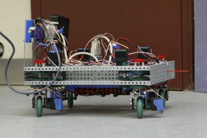
A detailed Mathematical Analysis of the Pivot-Wheel System is available in pdf format.During the Team 1640 2009 Summer Program, a Vex-scale 4-Wheel Pivot prototype was designed, built, programmed and tested. While Vex-scale, the prototype was equipped with an FRC cRIO controller. This provided realistic (FRC-like) control of the prototype, allowed an accurate assessment of control capabilities and problems, and also left us with transportable code and useful programming experience.
Our tests with this prototype were very satisfactory. Our test-driver, Carly, was particularly impressed with the robot's maneuverability in Crab and Snake modes (Automobile and Tank modes were much less interesting), and by the easy, intuitive control.
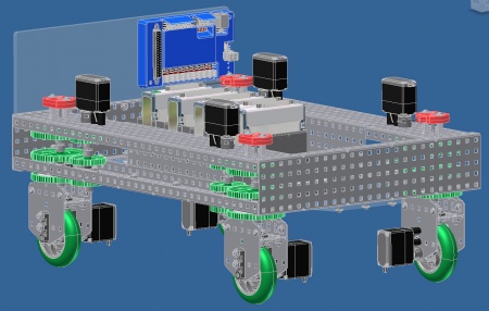
Based on our prototype trials, we decided to develop the design of a full-scale hypothetical Multi-Mode Pivot-Drive Chassis.
This is being pursued as a mental exercise.
Vex-Scale Prototype
The Vex-scale prototype possessed some limitations for our purposes. We understood and accepted these limitations, but they are important and so are cited here.
The chief limitation was the limited Pivot angle. In the interest of simplicity, coaxial wheel drive was not employed. In addition, potentiometers were selected to measure pivot angle. These potentiometers provided an absolute angle measurement, but were limited to 270° of rotation.A second limitation was the lack of an on-board battery. This meant that we had to operate teathered to a 12V FRC battery. Control, however, was wireless via the current FRC equipment.
The last limitastion was speed. The prototype used Vex motors and small wheels - ungeared.
Hypothetical FRC-scale Chassis
We designed a hypothetical 4-Wheel Pivot Drive Chassis using the following assumptions:
- The FRC Robot envelope would remain 28" x 38"
- The FRC Robot maximum mass would remain 120 lb excluding battery & bumpers
- Provisions for bumper attachment (and easy mounting and dismounting) was necessary
and the following performance bases:
- The Chassis would be truely multi-mode, capable of providing (at the driver's direction) true Crab, Snake, Automobile and Tank modes
- The Chassis would be intrinsicly bi-axial, capable of driving (again, at the driver's direction) along either the robot's long (x) or short (y) axes
The bases we set dictated some clear design decisions:
- In order to create a true Crab drive:
- Coaxial wheel drive is necessary; and
- Infinite pivoting is needed
- In order to create a multi-mode, multi-axis drive:
- Pivot angles and drive speeds need to be independently software controlled
- Pivot angles need to be driven by independent motors
- Wheels need to be driven by independent motors
- Therefore (4) drive and (4) steering motors are needed
- It is necessary to measure Pivot (Steering) angle for each wheel
- In order to create a true Crab drive:
View the Chassis (mk VI) Drawings.
Drive Train Details
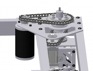
Each wheel is independently driven, with each drive design being identical (or mirrored). A CIM motor provides the drive power to each wheel via the following drive-train:
- The CIM drives a 10T Type 35 sprocket on its shaft
- driving the Pivot Drive Chain
- which drives the 28T Pivot Drive Sprocket
- which turns the Coaxial Drive Shaft from its top
- turning a Drive Miter Gear at its bottom
- which drives the Transfer Shaft Miter Gear
- thereby turning the Transfer Shaft
- and the 10T Transfer Shaft Sprocket
- driving the Wheel Drive Chain
- which drives the "Wheel" via the attached 22T "Wheel Drive Sprocket
Pivot Assemblies
The four Pivot Assemblies are identical.
Removal of a Pivot Assembly (mk VI) for service or replacement is straightforward.
- break and remove the Pivot Drive Chain
- remove the Pivot Drive Sprocket & key
- break and remove the Pivot Steering Chain
- remove the Pivot Retaining Ring
- the Pivot Assembly (including the bottom bearings and Steering Sprocket) will drop straight down and out of the Chassis


