DEWBOT VI Mechanical
From DEW Robotics

- DEWBOT VI’s scoring strategy is focused on scoring soccer balls. Towards this, we should be able to:
- Herd up to 3 soccer balls and push these into the goal if playing in the alliance zone
- Herd balls with the robot side as well and also push into the goal using the side.
- Kick the ball towards the goal. We expect to be able to reliably score from Mid-field and to at least be able to reliably move balls from the opposing zone to the alliance zone with a single kick over both bumps. Bonus if we can reliably score from the opposing zone.
- Clear soccer balls from the tunnels
- DEWBOT VI has no provisions to Elevate or Suspend.
- Ball centering is passive. We really want to kick on the move.
Kicker
- How do you move a soccer ball?
- How do you get a soccer ball you can't pick up into a goal?
- It's not a big surprise we ended up with a kicker on DEWBOT VI.
- The Kicker is latex-tubing powered. Kicker is 15” wide and had a kicking face tangent to the ball at the contact point.
- The Kicker will be cocked and fired pneumatically via the following sequence:
- Disarmed - Kicker in untensioned condition, such as after being fired
- Cock - a Main 2” bore, 4” stroke Cocking Cylinder with a 1.25" bore "helper" Cylinder extend to drive the Cocking Arm which in turn drives the Kicker into the fully-tensioned position. The Cocking Arm and Kicker pivot on the same axis.
- Latch - a ¾” bore, ½” stroke Latch Cylinder extends to close the Kicker Latch, holding the Kicker in the tensioned position
- Arm - The Cocking cylinders retract (only the "helper" cylinder is powered on the retraction, to conserve on air), retracting the Cocking Arm at the same time. The Kicker remains in the tensioned position due to the Latch.
- Fire - the Latch Cylinder retracts, opening the Latch and releasing the energy stored in the latex springs.
This sequence is illustrated in the following four (4) images. In these images, the Kicker is color-coded Cyan, the Cocking Arm is color-coded Olive; and the Latch is color-coded Violet.
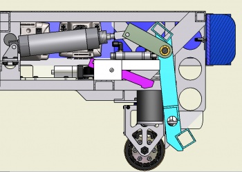
1 & 5) Kicker disarmed or fired
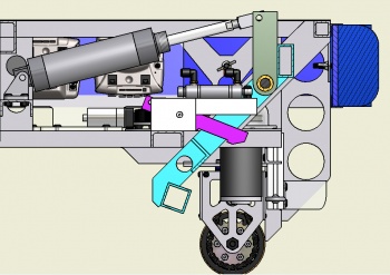
2) Kicker cocked
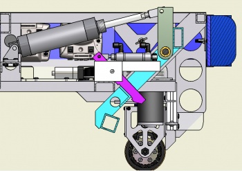
3) Kicker latched
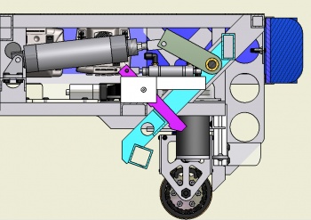
4) Kicker armed


- The Kicker power will not be adjustable during a match. It will be possible to adjust the latex tubing between matches to attenuate the Kicker’s power.
- The Kicker is a robust, welded aluminum assembly supported by a substantive welded structure within the chassis. Firing the Kicker releases a great deal of stored energy.
The Kicker must be disarmed prior to crossing the bump.
Kicker Development
- Kicker development proceeded in stages:
- Conceptual testing of several different kicker concepts using relatively simple prototypes to demonstrate feasibility.
- Refinement and testing of the selected concept - a latex-tube powered, swinging, wide kicker.
- Design and construction of intended Kicker and the design and construction of a proxy chassis into which the Kicker was installed. Kicker performance was verified. Cocking and Latching systems developed and tested. A Possessor tested. When we were satisfied with the Kicker System's overall performance, the System was transferred to the Robot.

- Concepts tested were:
- A motorized flywheel driven Kicker
- An air-spring Kicker based on a constrained, charged, 2" bore pneumatic cylinder. We really wanted this to work. It would have made our engineering jobs easier & happier.
- A latex-spring powered Kicker - the selected concept. It's just awesome, and awesome trumps easy any day. 'nuff said.
- Kicking cross-field (over both bumps) required (5) pre-tensioned latex bands. The 2" bore Cocking Cylinder had some difficulty tensioning this, so we added a "helper" Cylinder. First a 3/4" bore; then 1.25". A bonus of the "helper" Cylinder is that it can do the retraction by itself, thereby conserving compressed air.
- The Latch proved the most troublesome element to develop. High pressure on the latch contact surfaces either prevented release or resulted in unacceptably high wear rates. Steel was always used for these parts, but ultimately a piece of hardened tool steel was used for the catch plate. A couple of wire ties on the Latch provided a lubricous Latch surface which could be easily maintained.
Possessor
- The possessor went through a great deal of evolution and development.

- The first version of Possessor consisted of a 15" x 1¼" PVC pipe covered with grippy 1/16 neoprene rubber sheet shore 40 hardness. The roller was direct-driven by a Fisher Price motor attached to a Banes Bot 256:1, and later a 64:1 planetary gearbox. The latter gearbox provided an unloaded rotational velocity of about 4 revolutions/sec. This seemed to be effective on the static proxy chassis, but when mounted on the robot, it became clear that the possessor allowed the robot to ride up over the ball far too easily and was ineffective at possessing the ball. This original possessor was removed and replaced with a passive system just prior to shipping.
- The Team's experience at the Finger Lakes Regional, however, convinced us of the value of an effective possessor. We therefore resolved to revisit the concept. It was clear that both ball possession and centering was key for accurate and rapid scoring. It would allow us to spend less time lining up the robot to the ball and to the goal, and make it so we just have to align the robot + the ball to the goal.
- The problem of possessors pulling balls under the chassis was a common one at Finger Lakes. The main diet of robots seemed to be #9 soccer balls. We set to develop a possessor which would not eat soccer balls.
- The possessor system we developed utilized dual rollers:
- A powered possessor roller which would capture the ball. This was positioned as far forward on the frame as possible and contacted the ball near its top. This possessor roller is full robot width and belt-powered. We dropped a stage from the Bainbots (still using the FisherPrice motor) for an unloaded rotational speed of 19 rev/s. The possessor is a 1" OD Al tube.
- An unpowered back roller is located behing and below the possessor and serves as a back-stop for the ball. Should the possessor begin to eat the soccer ball, the back roller causes it to break contact with the ball. The back roller is a freely-rotating 1/2" aluminum rod.
- As for the possessor itself, we are currently still testing different materials for it. We have the correct height for possessing however as far as centering we are still testing gripping material vs. spacing.
- Current Materials to test with
- Green Polycord
- Elastic tubing
- Closed Cell Foam Pool Noodles
- The possessor is driven by a 4 stage gear box with 1 stage pinned out and 2 green polycords as drive belts.
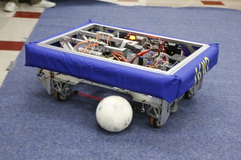
Sideguards
- A quick test revealed that DEWBOT VI easily drove over balls when driving towards then sideways. This would result in a penalty.
- Eyebolts and bungee sideguards were added to the robot side to prevent incursion of the balls under the frame. These sideguards do not interfere with crossing the bump. They do enable the robot to herd balls into the goal using the long chassis side.
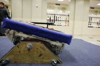
Crossing bump with sideguards in-place - no problem
Herding with robot side & sideguards. We can no longer drive over the balls from the sides.

