DEWBOT XI Internal Stacker
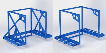
Our main scoring system allows us to build stacks of up to six Totes under a Recycle Container and to score these. This stack is built inside the robot chassis and we score by simply dropping the stack and backing up. This required a U-chassis, the scariest design element of DEWBOT XI.
Stacking Strategies
Analysis of this game makes it clear that in competitive matches, RCs will constrain scoring potential and maximizing the score per RC is therefore essential. The only sensible stacking strategy is therefore to:
- Pick up an RC
- Build an stack of six totes under the RC
- At some point in the process, put litter in the RC
- Score the stack and repeat the process
The resulting stack scores 42 points per RC, the maximum possible. The robot should produce as many of these stacks as possible.
Human Player Station versus Landfill loading: Ideally, be able to do both. We focused on Human Player station loading due to the perception that it would be faster. The 30 human player totes provide materials for 5 stacks.
U-Chassis
To minimize the stack's impact on robot center-of-mass, we decided to build the stack within the chassis. To score by simply dropping the stack and backing up to disengage, we determined to have no floor under the stack carried by the robot. These decisions led to a decision for a U-chassis, Sab-BOT-age's first. Form must follow function.This was our scariest design decision. From 2009, we have designed rugged welded chassis frames. How to do this for a U-chassis? Is this even possible?
To help overcome the intrinsic weaknesses of a U-chassis, we designed the chassis around a sturdy "backbone": a 41.5" long 2" x 2" x 0.125" wall 6061 Al square tube. This backbone was not cut for light-weighting, except at the very terminal ends.
Structural connections across the robot's back at different heights were also included to provide structural integrity. 1" x 1" x 0.125" wall 6061 Al square tube members were employed for this purpose.
Extensive diagonal bracing and gusseting was originally designed and planned. The need to rationalize weight led to a significant reduction in this bracing (with considerable trepidation).
Stacker
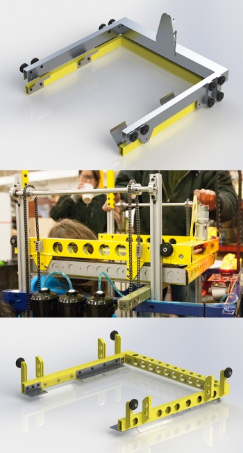
The stacker mechanism went through some evolution.- The original stacker concept provided 2-dimensional actuation: vertical for stacking totes & RC; and a horizontal fork to enable scoring of co-op stack points. Since the stacks were built inside the robot chassis, a separate mechanism was required to deposit coop totes on the step. As originally designed and built, this weighed 15.8 lb (excluding chain drive). An AndyMark 9012 motor with BaneBot 64:1 gearbox drove the coop fork.
- This stacker mechanism was aggressively weight reduced. Aluminum slides replaced the steel originals and lightweighting holes were cut. The steel spring clips to support the totes proved to be too springy and easily damaged by picking up the RC and were replaced by polycarbonate hinged support plates.
- The coop mechanism was never actually used. The decision to abandon this arrangement was driven by weight concerns and the understanding that if we were to be a stacker robot, we needed to do this well and without compromise. Prior to Hatboro-Horsham, the coop fork system was disabled and its drive motor removed.
- Between Hatboro-Horsham and Seneca, the entire original stacker assembly was replaced by a new, simpler and lighter assembly weighing 4.6 lb. Hinged supports were retained, but the forward section (bearing most of the tote weight) is 7075 Al. Spring steel tote aligners were included. This new stacker has a designed-in 2o back tilt for improved stack stability.
The stacker is raised and lowered via four chain runs of the Stacker Lift. Wheels on the stacker engage grooves in four (4) vertical 80/20 1010 profile sections, keeping the stacker accurately aligned with the robot chassis.
Stacker Lift
There are two independent stacker lift mechanisms: one for the left side; one for the right. These are not mechanically connected other than through the Stacker itself.
Each Stacker Lift mechanism comprises:
- A mini-CIM drive motor
- An AndyMark Toughbox Nano 12.75:1 Gearbox (am-0518) with aluminum gears replacing the two 50T steel gears
- A Digital Encoder on the gearbox
- The Gearbox output drives a 1/2" 7075 Al Lift Drive Shaft via #35 sprockets and steel roller chain
- The Lift Drive Shaft has two (2) #25 22T sprockets in addition to the #35 sprocket. The #25 sprockets each drive a #25 chain lift loop. The stacker is connected to the chain lift loops. An Idler Axle with another two (2) #25 22T sprockets supports the chain lift loop at the loops' top.
- The Lift Drive Shaft and Idler Axle are supported by bearings in bearing blocks which bolt to the 80/20 profiles which guide the stacker.
As initially built, the Gearbox drive sprocket was 9T while the driven sprocket was 15T. This resulted in a compound reduction of 21.25:1 from the mini-CIM to the Lift Drive Shaft; corresponding to a nominal unloaded lift speed of 26.6 in/s or a stall load (per side) of 270 lbf.
To increase the stacking speed, the gearing was modified at the beginning of MAR Championships so that the Gearbox drove a 15T sprocket; the 15T driven sprocket was retained. Compound reduction was 12.75:1 with the new sprockets; corresponding to a nominal unloaded lift speed of 44.3 in/s or a stall load (per side) of 163 lbf.
Of course, the system is neither unloaded nor stalled. The drivetrain model was modified to model the loaded lift (moving upwards only). Modeled loaded lift speed (12.75:1 total reduction) was 24 in/s.
The increased speed brought some issues as well as benefits (stacking was faster). When moving downwards, the stacker could accelerate faster than gravity could accelerate the totes and RC, which created a free-fall. The same problem occurred when the upward moving lift stopped. These zero-G issues were alleviated by adding software Gaussian ramps on the lift acceleration.
Another issue is that when the stacker engaged the lowest tote at this higher velocity, the impact put a lot of strain on the Aluminum stacker hinges, particularly the front hinges (which bear most of the load). This problem is not entirely resolved.
The Lift bearing blocks were designed specifically for this application, modeled on the

