Difference between revisions of "DEWBOT XVII Drive Train"
MaiKangWei (talk | contribs) (→Drive Transmission) |
MaiKangWei (talk | contribs) (→Hatboro-Horsham - The rubber hits the road and the road wins) |
||
| (26 intermediate revisions by the same user not shown) | |||
| Line 1: | Line 1: | ||
| − | [[image:DB17 Swerve 20220216a.jpg| | + | [[image:DB17 Swerve 20220216a.jpg|upright=1.1|right|frameless]][[image:DB17 Swerve 20220216b.jpg|upright=1.1|right|frameless]][[image:DB17 Swerve 20220216c.jpg|upright=1.1|right|frameless]][[image:DB17 Swerve 20220216d.jpg|upright=1.1|right|frameless]]Sab-BOT-age's 2022 swerve design was developed from the back-to-the drawing-board [[DEWBOT XVI Drive-Train|2020]] design, with the incorporation of some significant improvements. |
#) The drive transmission was simplified and reduced to 2-stages by relocating the NEO axis to the swerve rotational axis. | #) The drive transmission was simplified and reduced to 2-stages by relocating the NEO axis to the swerve rotational axis. | ||
| Line 6: | Line 6: | ||
CVT swerve, first employed in [[DEWBOT XIII Drive Train | DEWBOT XIII]] and used through [[DEWBOT XVI Drive-Train|DEWBOT XVI]], was not employed. | CVT swerve, first employed in [[DEWBOT XIII Drive Train | DEWBOT XIII]] and used through [[DEWBOT XVI Drive-Train|DEWBOT XVI]], was not employed. | ||
| + | |||
| + | Swerve module weight is down to 4.3 lb<sub>m</sum>. | ||
Access [[Media:PivotAssembly20212022.zip|'''zipped 2022 swerve module SolidWorks files''']]. | Access [[Media:PivotAssembly20212022.zip|'''zipped 2022 swerve module SolidWorks files''']]. | ||
| Line 34: | Line 36: | ||
#) Synchronous pulley (HTD5) reduction 11:60 | #) Synchronous pulley (HTD5) reduction 11:60 | ||
| − | Focus is on minimizing steering backlash. | + | Focus is on minimizing steering backlash. All this is just like the [[DEWBOT XVI Drive-Train|DEWBOT XVI]] swerve module. |
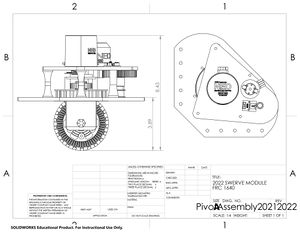
| − | + | [[image:PivotAssembly2022.jpg|300px|left]]But the steering angle measurement is completely different. A Lamprey Hall-Effect encoder is suspended from the top plate coaxial with the NEO and rotational axis. This interacts with a magnet mounted on a platform built up from the swerve rotational element, with the magnet also coaxial with the rotational axis. So, for the first time ever, we are actually measuring the angle of the steering directly rather than through a proxy. You've gotta' love it! | |
==Structural Changes== | ==Structural Changes== | ||
| − | + | The bottom plate, which bears the weight of the robot and shock loads, is ¼" G-10 fiberglass composite. This has been redesigned to mount in a chassis frame corner. Previously, this plate has mounted left and right, requiring the addition of a longitudinal beam inboard of the frame perimeter to support the swerve modules. This change enables us to eliminate this longitudinal and to design any interior frame elements based on the needs of scoring elements instead of propulsion. | |
| − | + | Swerve modules are installed in each corner with different orientations, each advancing 90° as you go around the chassis. This departs from previous practice (except for the legendary [[media:Tribot_white_paper.pdf|Tribot]]). | |
| − | + | ==Manufacturing== | |
| − | + | Top plate is printed from high-strength polycarbonate. Some white & some black. Because we ran out of whichever we started with. | |
| − | == | + | ==Hatboro-Horsham - The rubber hits the road and the road wins== |
| + | The new swerve modules experienced serious reliability and durability problems at Hatboro-Horsham, our 1<sup>st</sup> competition. The key problems that surfaced were: | ||
| + | #) The Lamprey Encoders repeatedly lost calibration. This created huge driving problems during many matches. | ||
| + | #) The Lamprey Encoders are fragile, particularly the magnets. They broke. | ||
| + | #) The 3½" bearing supporting the rotating elements of the swerve module was insufficiently secured and bearing was able to be forced out its mounting. | ||
| + | |||
| + | While it was the fall from the TRANSVERSAL RUNG at the end of Semifinals which unrecoverably put DEWBOT XVII out of action, by that point we were entirely out of spare swerves. We burned through them during the event and at the end struggled to keep four awerve modules working. | ||
| + | |||
| + | The Lamprey Encoder problem was resolved by going back to the old BI Technologies Magnepot Hall Effect Potentiometer Part # [http://www.bitechnologies.com/pdfs/6120.pdf 6127V1A360L.5FS]. This utilizes a separate shaft geared 1:1 from the rotating swerve unit. 1640 has long and positive experience with the BI encoder. | ||
| + | The 3½" bearing mounting was made more secure by the addition of washers around the securing bolt heads, thereby increasing the support contact surface. | ||
| + | The swerve modules performed without trouble at Springside Chestnut Hill Academy. | ||
---- | ---- | ||
| − | [[Category:DEWBOT | + | [[Category:DEWBOT XVII]][[Category:Drive-train]][[Category:Swerve Drive]][[Category:Engineering]] |
Latest revision as of 19:37, 22 March 2022
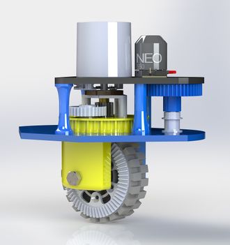
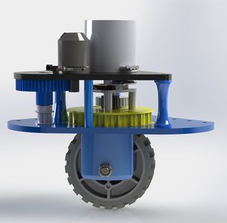
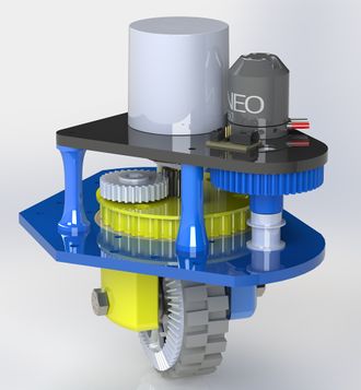
Sab-BOT-age's 2022 swerve design was developed from the back-to-the drawing-board 2020 design, with the incorporation of some significant improvements.- ) The drive transmission was simplified and reduced to 2-stages by relocating the NEO axis to the swerve rotational axis.
- ) For the first time, the steering angle is measured directly rather than by proxy.
- ) The module is now frame-corner mounted.
CVT swerve, first employed in DEWBOT XIII and used through DEWBOT XVI, was not employed.
Swerve module weight is down to 4.3 lbm</sum>.
Access zipped 2022 swerve module SolidWorks files.
Contents
Power Plants
A NEO powers the drive. Steering power provided by a NEO 550.
Drive Transmission
The drive transmission was simplified to 2 stages with a fixed gear ratio. To accomplish this, the NEO had to be relocated to make it coaxial with the rotating elements. There's no pinion. The 2022 transmission comprised:
- ) A 15T spur gear driving a 29T spur gear - 2.5:1 reduction. Both gears are steel - 1.93:1 reduction.
- ) A 15T bevel gear driving a 60T bevel gear bolted to a 4" diameter wheel. Also both steel - 4:1 reduction.
Overall drive reduction is 7.73:1.
Overall reduction can be varied by changing the 1st stage gears (maintaining a 44 tooth count for the sum of the gears). For example:
- 14T:30T for 8.57 reduction
- 15T:29T for 7.73 reduction
- 16T:28T for 7.00 reduction
- 18T:26T for 5.78 reduction
Steering Transmission & Sensing
Steering is reduced 43.6:1 in 2 stages:
- ) A 6T Pinion drives a 48T spur gear (20 DP; 14° contact angle). The pinion is steel, while the 48T gear is printed PETG.
- ) Synchronous pulley (HTD5) reduction 11:60
Focus is on minimizing steering backlash. All this is just like the DEWBOT XVI swerve module.
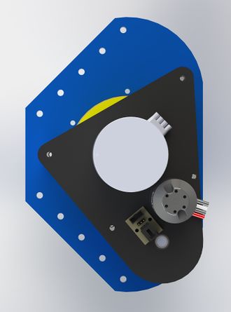
But the steering angle measurement is completely different. A Lamprey Hall-Effect encoder is suspended from the top plate coaxial with the NEO and rotational axis. This interacts with a magnet mounted on a platform built up from the swerve rotational element, with the magnet also coaxial with the rotational axis. So, for the first time ever, we are actually measuring the angle of the steering directly rather than through a proxy. You've gotta' love it!Structural Changes
The bottom plate, which bears the weight of the robot and shock loads, is ¼" G-10 fiberglass composite. This has been redesigned to mount in a chassis frame corner. Previously, this plate has mounted left and right, requiring the addition of a longitudinal beam inboard of the frame perimeter to support the swerve modules. This change enables us to eliminate this longitudinal and to design any interior frame elements based on the needs of scoring elements instead of propulsion.
Swerve modules are installed in each corner with different orientations, each advancing 90° as you go around the chassis. This departs from previous practice (except for the legendary Tribot).
Manufacturing
Top plate is printed from high-strength polycarbonate. Some white & some black. Because we ran out of whichever we started with.
Hatboro-Horsham - The rubber hits the road and the road wins
The new swerve modules experienced serious reliability and durability problems at Hatboro-Horsham, our 1st competition. The key problems that surfaced were:
- ) The Lamprey Encoders repeatedly lost calibration. This created huge driving problems during many matches.
- ) The Lamprey Encoders are fragile, particularly the magnets. They broke.
- ) The 3½" bearing supporting the rotating elements of the swerve module was insufficiently secured and bearing was able to be forced out its mounting.
While it was the fall from the TRANSVERSAL RUNG at the end of Semifinals which unrecoverably put DEWBOT XVII out of action, by that point we were entirely out of spare swerves. We burned through them during the event and at the end struggled to keep four awerve modules working.
The Lamprey Encoder problem was resolved by going back to the old BI Technologies Magnepot Hall Effect Potentiometer Part # 6127V1A360L.5FS. This utilizes a separate shaft geared 1:1 from the rotating swerve unit. 1640 has long and positive experience with the BI encoder.
The 3½" bearing mounting was made more secure by the addition of washers around the securing bolt heads, thereby increasing the support contact surface.
The swerve modules performed without trouble at Springside Chestnut Hill Academy.
