Difference between revisions of "DEWBOT X Drive Train"
MaiKangWei (talk | contribs) (Created page with 'of Ultimate Ascent, the team decided on 11-January to utilize pivot drive again. In addition, to maximize agility, this drive would utilize our new Oce...') |
MaiKangWei (talk | contribs) (→Driving straight in autonomous) |
||
| (20 intermediate revisions by the same user not shown) | |||
| Line 1: | Line 1: | ||
| − | of | + | [[Image:DBX_140201_csm-1.jpg|right|frameless|upright=1.1]][[Image:DBX_140208_csm-6.jpg|right|frameless|upright=1.1]]Due to the very strong expected defensive nature of Aeriel Assist, and serious bandwidth limitations on our design team, we made the decision on 5-January to utilize [[DEWBOT IX Drive Train | DEWBOT IX's Drive Train design]] (which has been published) with a couple important upgrades. |
==Issues with the 2013 pivot design== | ==Issues with the 2013 pivot design== | ||
| Line 5: | Line 5: | ||
Our 2013 robot, [[DEWBOT IX]], participated in more competitions, demos and driver practice than any robot before it (we said this last year, but it is true again this year). That said, the 2013 pivots performed extremely well, but the following issues were observed: | Our 2013 robot, [[DEWBOT IX]], participated in more competitions, demos and driver practice than any robot before it (we said this last year, but it is true again this year). That said, the 2013 pivots performed extremely well, but the following issues were observed: | ||
| − | :# One Pivot tube/Pivot Top weld failed in 2013 (in off-season competition), resulting in the total constructive loss of the pivot module. | + | :# One Pivot tube/Pivot Top weld failed in 2013 (in off-season competition), resulting in the total constructive loss of the pivot module |
| − | :# One Igus bushing came loose from the module top plate. Repaired. | + | :# One miter gear fell off its coaxial drive shaft (off-season). Repairable but not repaired. |
| − | :# Occasional loss of calibration was were | + | :# One Igus bushing came loose from the module top plate (off-season). Repaired. |
| + | :# Occasional loss of calibration was experienced due to slippage of the angle sensors' fiberglass flex couplings' set screws. | ||
| + | :# Driving straight during autonomous was not possible without at least two (catecorner) pivots equipped with tachometers - 2013 pivots were tachometer-ready, but only tachometer-equipped for development trials. | ||
| + | |||
| + | ==Developments on the 2013 pivot design== | ||
| + | |||
| + | [[image:DBX_140209_csm-2.jpg|250px|right|thumb|Ruland clamp-type Beam Coupling]]Development of the 2014 pivot design was really the development of sensors and software necessary to enable the robot to drive straight in autonomous. [[User:Gdeaver | Gary Deaver]] led the sensor development while Patrick D led software development. | ||
| + | |||
| + | The following design changes were made: | ||
| + | :* All pivot modules are tachometer-equipped | ||
| + | :* All motor power wires terminate in 4-conductor 40-amp Anderson Connectors (no more disconnecting at the motor controllers) | ||
| + | :* All sensor wires terminate at dual PWM connectors | ||
| + | :* Ruland FRC12-4-4-A (FIRST Choice) clamp-type 6-beam couplings replace the old fiberglass set-screw couplings | ||
| + | :* 2024 AL replaces 6061 AL for the pivot module bottom plate | ||
| + | :* 3/8"-16 x 4" steel axle studs replace 2013's cut-down 4.5" axles | ||
| + | |||
| + | ==Tachometers== | ||
| + | |||
| + | In lieu of encoders, which provide more data than needed, it was decided that we would develop tachometers (similar to those used for bicycles) to measure pivot drive speed and distance. | ||
| + | |||
| + | Six (6) neodymium magnets were secured equally spaced around the lower rim of the 56T coaxial drive pulley. A coil pickup is mounted on the pivot module top plate in a position directly below the arc of the magnets. All pivots are tachometer-equipped. | ||
| + | |||
| + | The angular distance between magnets corresponds to 0.785 in of robot travel. | ||
| + | |||
| + | <gallery widths=350 heights=250 perrow=2> | ||
| + | image:DBX_140128_csm-11.jpg|Magnets on underside of 56T pulley | ||
| + | image:DBX_140209_csm-1.jpg|Tachometer sensor | ||
| + | </gallery> | ||
==Value Engineering== | ==Value Engineering== | ||
| − | [[image: | + | [[image:Value_Engineering_2014.jpg|400px|right]]Value engineering seeks to widen the gap between the value a product provides to the customer and its cost. Value and cost in this context includes both monetary and non-monetary measures. For example, addressing the issues listed above increases the value of the product to the customer (drive team & pit crew). Cost includes monetary cost (measured following FRC cost guidelines) but also mass, manpower and machine time. |
Each Autumn, we conduct a value engineering exercise on our pivot drive design to understand what changes we would make if we were to select pivot drive again. The results of this exercise are summarized in the accompanying Table. | Each Autumn, we conduct a value engineering exercise on our pivot drive design to understand what changes we would make if we were to select pivot drive again. The results of this exercise are summarized in the accompanying Table. | ||
| − | + | This year, between the Tachometer, Anderson Connectors and our conservative design approach, the pivot modules put on a little weight. Careful buying (and FIRST CHOICE) yielded some small dollar savings despite the utility improvements. | |
| − | |||
| − | |||
| − | |||
| − | |||
| − | |||
| − | |||
| − | |||
| − | |||
| − | |||
| − | |||
| − | |||
| − | |||
| − | |||
| − | |||
| − | |||
| − | |||
| − | |||
| − | |||
| − | |||
==Pivot Module [[media:Swerve_1640_2013.zip | CAD Design]] and [[media:Swerve_BoM_2013.xls | Bill of Materials]]== | ==Pivot Module [[media:Swerve_1640_2013.zip | CAD Design]] and [[media:Swerve_BoM_2013.xls | Bill of Materials]]== | ||
| − | ==Calibration - no change from [[DEWBOT VIII Drive Train#Pivot Calibration | | + | ==Calibration - no change from [[DEWBOT VIII Drive Train#Pivot Calibration | 2012]]== |
==Chassis & Wheel-base== | ==Chassis & Wheel-base== | ||
| − | Chassis was once again welded 6061 Al. Mostly 1" x 2" x 0.130" U-Channel. | + | Chassis was once again welded 6061 Al. Mostly 1" x 2" x 0.130" U-Channel. Our 2011 chassis design served as the starting-off point for the design. |
| + | |||
| + | Wheelbase is 21" (nominally wide) x 22.25" (nominally long). Chassis exterior dimensions are 27.75" x 27.75". All these values are identical to 2013's robot | ||
| − | + | ==Driving straight in autonomous== | |
| + | We finally managed this trick in time for MAR Championship. A gyroscope provided the necessary input to a proportional loop which steered the front wheel pivots. A tremendous success. | ||
---- | ---- | ||
| − | [[Category:Robot]][[Category:DEWBOT X]][[Category:Drive-train]][[Category: | + | [[Category:Robot]][[Category:DEWBOT X]][[Category:Drive-train]][[Category:Swerve Drive]][[Category:Photo Galleries]] |
Latest revision as of 12:28, 27 January 2015


Contents
Issues with the 2013 pivot design
Our 2013 robot, DEWBOT IX, participated in more competitions, demos and driver practice than any robot before it (we said this last year, but it is true again this year). That said, the 2013 pivots performed extremely well, but the following issues were observed:
- One Pivot tube/Pivot Top weld failed in 2013 (in off-season competition), resulting in the total constructive loss of the pivot module
- One miter gear fell off its coaxial drive shaft (off-season). Repairable but not repaired.
- One Igus bushing came loose from the module top plate (off-season). Repaired.
- Occasional loss of calibration was experienced due to slippage of the angle sensors' fiberglass flex couplings' set screws.
- Driving straight during autonomous was not possible without at least two (catecorner) pivots equipped with tachometers - 2013 pivots were tachometer-ready, but only tachometer-equipped for development trials.
Developments on the 2013 pivot design
Development of the 2014 pivot design was really the development of sensors and software necessary to enable the robot to drive straight in autonomous. Gary Deaver led the sensor development while Patrick D led software development.
The following design changes were made:
- All pivot modules are tachometer-equipped
- All motor power wires terminate in 4-conductor 40-amp Anderson Connectors (no more disconnecting at the motor controllers)
- All sensor wires terminate at dual PWM connectors
- Ruland FRC12-4-4-A (FIRST Choice) clamp-type 6-beam couplings replace the old fiberglass set-screw couplings
- 2024 AL replaces 6061 AL for the pivot module bottom plate
- 3/8"-16 x 4" steel axle studs replace 2013's cut-down 4.5" axles
Tachometers
In lieu of encoders, which provide more data than needed, it was decided that we would develop tachometers (similar to those used for bicycles) to measure pivot drive speed and distance.
Six (6) neodymium magnets were secured equally spaced around the lower rim of the 56T coaxial drive pulley. A coil pickup is mounted on the pivot module top plate in a position directly below the arc of the magnets. All pivots are tachometer-equipped.
The angular distance between magnets corresponds to 0.785 in of robot travel.
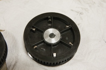
Magnets on underside of 56T pulley
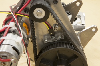
Tachometer sensor


Value Engineering

Each Autumn, we conduct a value engineering exercise on our pivot drive design to understand what changes we would make if we were to select pivot drive again. The results of this exercise are summarized in the accompanying Table.
This year, between the Tachometer, Anderson Connectors and our conservative design approach, the pivot modules put on a little weight. Careful buying (and FIRST CHOICE) yielded some small dollar savings despite the utility improvements.
Pivot Module CAD Design and Bill of Materials
Calibration - no change from 2012
Chassis & Wheel-base
Chassis was once again welded 6061 Al. Mostly 1" x 2" x 0.130" U-Channel. Our 2011 chassis design served as the starting-off point for the design.
Wheelbase is 21" (nominally wide) x 22.25" (nominally long). Chassis exterior dimensions are 27.75" x 27.75". All these values are identical to 2013's robot
Driving straight in autonomous
We finally managed this trick in time for MAR Championship. A gyroscope provided the necessary input to a proportional loop which steered the front wheel pivots. A tremendous success.