Difference between revisions of "3-Wheel Swerve"
MaiKangWei (talk | contribs) |
MaiKangWei (talk | contribs) |
||
| Line 7: | Line 7: | ||
Image:Tribotwood3.jpg|Prototype design based on 111" geometry showing electronics locations | Image:Tribotwood3.jpg|Prototype design based on 111" geometry showing electronics locations | ||
Image:Roundbot111.jpg|Equilateral swerve in a round chassis on 111" perimeter | Image:Roundbot111.jpg|Equilateral swerve in a round chassis on 111" perimeter | ||
| − | Image:Tribotwood4.jpg| | + | Image:Tribotwood4.jpg|Equilateral design |
Image:Pentabot111.jpg|Pentagonal design based on 111" perimeter. Casters to be located at the (2) vacant positions to improve stability. | Image:Pentabot111.jpg|Pentagonal design based on 111" perimeter. Casters to be located at the (2) vacant positions to improve stability. | ||
Image:Tribot_130711_csm.jpg|Pentagonal prototype | Image:Tribot_130711_csm.jpg|Pentagonal prototype | ||
Revision as of 00:17, 5 August 2013
The 2013 change in perimeter rules (112 in overall perimeter vis-à-vis 28in x 38 in) open new potentials for non-rectangular robots. The team decided to explore this.
In particular, the new rules enable the design of a 3-wheeled robot without paying as large a penalty in terms of reduced stability. Potential benefits of a 3-wheeled drive-train are reduced drive-train and chassis weight, and/or a drive-train with enhanced features (which might otherwise been impractical due to drive-train weight). Additionally, a 3-wheeled swerve robot reduce burden on the cRIO. A tiangular chassis robot may be able to break a blockage by opposing robots more easily than a rectangular chassis robot due to the reduced corner angle.
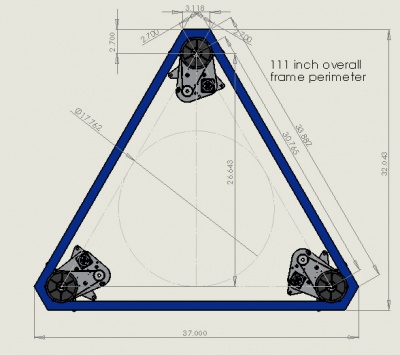
Equilateral triangle design on 111" perimeter
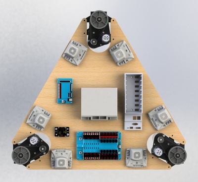
Prototype design based on 111" geometry showing electronics locations
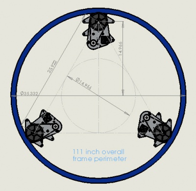
Equilateral swerve in a round chassis on 111" perimeter
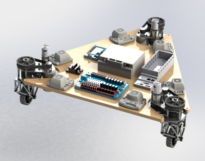
Equilateral design
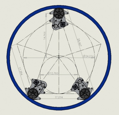
Pentagonal design based on 111" perimeter. Casters to be located at the (2) vacant positions to improve stability.
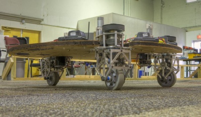
Pentagonal prototype


