Difference between revisions of "DEWBOT VIII Bridge Manipulation"
MaiKangWei (talk | contribs) (Created page with '1640's Bridge manipulation requirements for Rebound Rumble are: * Wide chassis orientation to facilitate triple balancing * Center of mass low enough to prevent robot tipping on ...') |
MaiKangWei (talk | contribs) |
||
| (51 intermediate revisions by the same user not shown) | |||
| Line 1: | Line 1: | ||
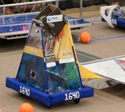
| − | 1640's Bridge manipulation requirements for Rebound Rumble are: | + | [[image:DB8_IRI_120721_csm-4.jpg|400px|right|thumb|Triple balanced with [http://www.redalert1741.org/ 1741] & [http://www.thunderchickens.org/ 217] at [[DEWBOT VIII Indiana Robotics Invitational| IRI]]]]1640's Bridge manipulation requirements for Rebound Rumble are: |
* Wide chassis orientation to facilitate triple balancing | * Wide chassis orientation to facilitate triple balancing | ||
* Center of mass low enough to prevent robot tipping on inclined and dynamic bridge with robot in the wide orientation | * Center of mass low enough to prevent robot tipping on inclined and dynamic bridge with robot in the wide orientation | ||
| Line 13: | Line 13: | ||
From a game-play standpoint, the Bridge is '''HUGE'''. Both in qualifications (where the coopertition bridge is critical for Qualification Score) and in eliminations (where triple balancing makes an alliance tough to beat), being able to control the bridge and balancing is a critical aspect for success in Rebound Rumble. We ended up being a pretty competent bridge robot (but not best in class). | From a game-play standpoint, the Bridge is '''HUGE'''. Both in qualifications (where the coopertition bridge is critical for Qualification Score) and in eliminations (where triple balancing makes an alliance tough to beat), being able to control the bridge and balancing is a critical aspect for success in Rebound Rumble. We ended up being a pretty competent bridge robot (but not best in class). | ||
| + | |||
| + | ==Key Technical Challenges== | ||
| + | * Our 4-wheel drive-train does not allow us to hang off the edge of the bridge safely | ||
| + | * Our shooter is high; a lower center-of-mass would have been beneficial for balancing (especially triple balancing) | ||
| + | * High center-of-mass, wide orientation and 4-wheel drive-train means that we cannot be the last robot on the bridge in a triple balance (we flip over backwards) | ||
| + | * A stinger would therefore make no sense for us | ||
| + | * The decisions for pivot drive and [[DEWBOT_VIII_Drive_Train#Barrier_Wheel_Drive_Transmission | barrier crossing]] lead to a decision to forgo pneumatics to manage robot mass - pneumatics would have been very useful for bridge manipulation | ||
| + | * The decision to cross the barrier with pivot drive also committed a lot of brain time to the drive train and chassis design | ||
| + | * The hopper and lift made it really difficult to transfer power left-to-right across the robot | ||
| + | |||
| + | ==Concepts (Gen 1 - Build Season)== | ||
| + | * Bridge manipulation would be accomplished by an angled protrusion (Bridge Arm) on the robot front - when the robot ran into the bridge, the Bridge Arm would push the bridge down, allowing the robot to mount the bridge | ||
| + | * Force to push the bridge down would be provided by the robot's motion | ||
| + | * The Bridge Arm would be articulated with two positions - no protrusion when raised - able to push the bridge down when lowered | ||
| + | * Limit switches to control the two positions | ||
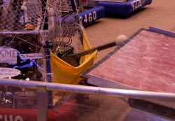
| + | * The Bridge Arm would support a lycra hopper for top loading - when bridge arm is deployed, the hopper is open for Outbounder feed | ||
| + | |||
| + | ==Prototypes== | ||
| + | <gallery widths=250 heights=250 perrow=3> | ||
| + | Image:DB8_120114_csm-7.jpg|First prototype mounted on [[DEWBOT VII]] (''deux'') chassis for testing | ||
| + | Image:DB8_120122_csm-18.jpg|Screw deployment parts for bridge arm | ||
| + | Image:DB8_120129_skm.jpg|Robot CAD layout showing deployed bridge arm, chassis, lift & shooter | ||
| + | Image:DB8_120130_csm-9.jpg|Rich Kulik designing bridge arm | ||
| + | Image:Robot_120205.jpg|More developed CAD layout showing hopper geometry | ||
| + | Image:DB8_120208_csm-6.jpg|Prototype testing using [[DEWBOT VIII]] chassis | ||
| + | </gallery> | ||
| + | |||
| + | ==Design Details== | ||
| + | A single window motor powered the bridge arm by turning a 1/2" diameter lead screw. Original plans to power deploy the bridge arm on both sides were abandoned due to mechanical complexity and mass constraints. | ||
| + | |||
| + | Two limit switches were employed to stop deployment either open or closed. | ||
| + | |||
| + | <gallery widths=250 heights=250 perrow=3> | ||
| + | Image:DB8_120219_csm-10.jpg|Prototype arm (one side only) with complete deployment mechanism showng two arms | ||
| + | Image:DB8_120225_csm-4.jpg|Original bridge arm complete excluding hopper | ||
| + | Image:DB8_HH_bridge_arm_120302_csm.jpg|Original bridge arm deployed at [[DEWBOT VIII Hatsboro-Horsham | Hatboro-Horsham]] | ||
| + | </gallery> | ||
| + | |||
| + | ==Issues & Developments== | ||
| + | While many 2012 robots successfully used an angled robot velocity driven bridge arm to manipulate the bridge, DEWBOT VIII's original bridge arm was not successful in lowering the bridge. The problem stemmed from the height of the arm's pivot point, which had to allow clearance for bridge crossing. This issue was discovered during build season and in an effort to correct this, a second arm was deployed to further depress the bridge. The angle of this second arm, however, was too steep to drive the bridge down (the robot stopped). As a result, we were not able to control the bridges at [[DEWBOT VIII Hatsboro-Horsham | Hatboro-Horsham]]. | ||
| + | |||
| + | In retrospect, we always tested this bridge arm cautiously and at a quite low robot velocity. Based on observations of other robots during the 2012 season, approaching the bridge at a higher velocity (with or without the second arm) would have been likely to either succeed or result in a damaged bridge arm. This was never tried. | ||
| + | |||
| + | ===Gen 2 ([[DEWBOT VIII Lenape | Lenape]])=== | ||
| + | Following [[DEWBOT VIII Hatsboro-Horsham | Hatboro-Horsham]], we implimented an entirely different bridge manipulation approach. The new manupulator was an active arm driven through about 120° of arc which pushed the bridge down using the drive motor's force (in lieu of robot motion). | ||
| + | |||
| + | A Denso motor (Window Motor Left - 262100-3040) was used directly driving a 9T Type 35 sprocket. An axle extended from the 9T sprocket to a bearing block in the facing instrument panel, so the 9T sprocket was supported both sides. The 9T sprocket drove a 62-link type 35 chain and thereby a 54T sprocket, to which the bridge arm was attached. | ||
| + | |||
| + | The 6:1 sprocket reduction with the Denso motor provides a stall torque on the bridge arm pivot of 47 ft lb<sub>f</sub> with an unloaded rotational speed of 0.23 rev/s. With an arm length of 16.6in (pivot to bridge contact) the arm can apply a tangential force of up to 34 lb<sub>f</sub>. | ||
| + | |||
| + | The 54T sprocket and bridge arm rotated on a dead axle cantilevered from a bracket on one side. On the unsupported side, a flexible connector linked the sprocket to a [http://datasheet.octopart.com/981HE0B4WA1F16-Vishay-datasheet-6387172.pdf Vishay 981HE0B4WA1F16] absolute encoder angle sensor. The flexible connector was originally latex tubing, but later changed to a fiberglass flexible coupling (GJ-6D from Automation Direct). The angle sensor was initially secured to the electronics panel via standoff, but later secured via a flexible polypropylene bracket connected to the bridge arm bracket. | ||
| + | |||
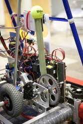
| + | The original bridge arm was a length of 1" x 1/8" wall square fiberglass pultrsion with a tennis ball on the end. At [[DEWBOT VIII Lenape | Lenape]], this evolved to a 1¼" x 1/8" wall square 304SS square tube with 1.5 lb<sub>m</sub> of molten zinc poured into the far end and a pair of nylon wheels on the far end. The heavy steel square tube with zinc filler served as an active balancing arm, which proved quite useful at [[DEWBOT VIII FRC Championship | Championship]]. At Championship, we also introduced a new 1" x 1/8" wall steel arm equipped with a latching hook (to secure to other robots, thereby facilitating triple balancing) and nylon wheels. | ||
| + | |||
| + | This arrangement worked (sometimes), but suffered from serious reliability problems: | ||
| + | :* The cantilevered arrangement of the bridge arm and sprocket assembly caused this assembly to wobble relative to the robot - a lot | ||
| + | :* This wobble put a lot of strain on the flexible connection between the driven sprocket and the angle sensor. Sometimes the flexible connection broke. Sometimes it simply lost calibration. Occasionally the angle sensor broke. Any one of these failures rendered the bridge arm unusable and required maintenance and recalibration. | ||
| + | :* The forces applied to the bridge arm would also occasionally bend the bridge arm bracket | ||
| + | At [[DEWBOT VIII Mid-Atlantic Region Championship | Philadelphia]], these problems caused the bridge arm to be out of service in about half of our matches. At [[DEWBOT VIII Bridgewater-Raritan Battle Royale | [BR]<sup>2</sup>]], niether of the robots we entered into the competition had working bridge arms. | ||
| + | |||
| + | The key weaknesses were identified as: | ||
| + | :# The bridge arm axle should be supported on both sides of the driven sprocket | ||
| + | :# The bridge arm axle should be live and should engage the angle sensor directly | ||
| + | :# The angle sensor mount should be part of the bridge arm axle support assembly | ||
| + | |||
| + | <gallery widths=250 heights=250 perrow=3> | ||
| + | Image:DB8_bridge_arm_bracket_120311_csm.jpg|Original prototype mounted on ''Deux'' for testing | ||
| + | Image:DB8_bridge_arm_bracket_120314_csm.jpg|Molly with 54T sprocket | ||
| + | Image:DB8_bridge_arm_bracket_120318_csm-1.jpg|Andrew & Yahya assemble the bridge arm drive | ||
| + | Image:DB8_bridge_arm_bracket_120318_csm-2.jpg|New (fiberglass pultrusion) bridge arm on ''Prime'' | ||
| + | Image:DB8_bridge_arm_bracket_120426_csm.jpg|Pushing bridge up at [[DEWBOT VIII FRC Championship | Championship]] with the 304SS arm | ||
| + | Image:DB8_bridge_arm_bracket_120427_csm.jpg|Pushing bridge down at [[DEWBOT VIII FRC Championship | Championship]] | ||
| + | </gallery> | ||
| + | |||
| + | ===Gen 3 ([[DEWBOT VIII Indiana Robotics Invitational | IRI]])=== | ||
| + | Significant structural improvements were made to the bridge arm mechanism between [[DEWBOT VIII Bridgewater-Raritan Battle Royale | [BR]<sup>2</sup>]] and the [[DEWBOT VIII Indiana Robotics Invitational | IRI]] competition to addess the observed mechanical and control weaknesses. | ||
| + | :* The bridge arm rotation shaft was supported securely on both sides | ||
| + | :* The bridge arm rotation shaft was changed from a dead axle to a live axle - the live axle drives the angle sensor | ||
| + | :* Polymer (Derlin) bushings replaced ball bearings | ||
| + | :* A substantive 3/8" Al axle is employed for the rotation shaft, with an integral mount provided for the angle sensor shaft | ||
| + | :* The new bridge arm bracket includes a secure mount for the angle sensor mounting plate | ||
| + | :* The angle sensor mounting plate is identical in design to [[DEWBOT VII Drive Train#Angle sensor & calibration | DEWBOT VII's]] - at IRI this was in fact a [[DEWBOT VII]] spare (made of polycarbonate) but this was subsequently replaced with a machined brass piece (mechanically identical) to reduce flexure | ||
| + | :* No change to motor, chain or sprockets | ||
| + | :* Captain Jas. Hook's bridge arm was mounted - We had, alas, no takers at IRI (cannot imagine why) | ||
| + | |||
| + | The new bracket is a substantive machined aluminum part. Before fabricating the aluminum bracket, the piece was printed using a 3D printer, assembled in place and tested. This was the team's first experience with a 3D printed part. | ||
| + | <gallery widths=250 heights=250 perrow=3> | ||
| + | Image:DB8_bridge_arm_bracket_120620_csm-1.jpg|Kira with printed prototype bridge arm bracket | ||
| + | Image:DB8_bridge_arm_bracket_120620_csm-2.jpg|Printed prototype bridge arm bracket installed for testing on ''Deux'' | ||
| + | Image:DB8_bridge_arm_bracket_120627_csm-1.jpg|New Bridge Arm Bracket - as used at [[DEWBOT VIII Indiana Robotics Invitational | IRI]] - note polycarbonate sensor mount from [[DEWBOT VII]] | ||
| + | Image:DB8_bridge_arm_bracket_120815_csm-1.jpg|New Bridge Arm Bracket - sensor side view | ||
| + | Image:DB8_bridge_arm_bracket_120815_csm-2.jpg|New Bridge Arm Bracket - motor side view | ||
| + | Image:DB8_bridge_arm_bracket_120815_csm-3.jpg|Sensor mount detail - note brass sensor mount | ||
| + | </gallery> | ||
| + | |||
| + | ---- | ||
| + | [[Category:Robot]][[Category:DEWBOT VIII]][[Category:Photo Galleries]] | ||
Latest revision as of 00:23, 7 September 2012
1640's Bridge manipulation requirements for Rebound Rumble are:
- Wide chassis orientation to facilitate triple balancing
- Center of mass low enough to prevent robot tipping on inclined and dynamic bridge with robot in the wide orientation
- Pivot "brake" to prevent movement on bridge after achieving balance
- Ability to quickly and certainly lower the bridge to enable mounting from a robot wide side
- The original bridge manipulation mechanism was integrated into the top loading ball hopper
Additional nice to haves were identified after gaining some competition experience:
- Bridge arm can be used to influence center of mass and therefore balance
- There is value in being able to push the bridge up as well as down
- A hook could be employed to link robots to enable hanging off the bridge edge in triple balancing
DEWBOT VIII's bridge manipulation approach & mechanisms witnessed the greatest changes of any functional area during the competition season. Also the greatest improvement.
From a game-play standpoint, the Bridge is HUGE. Both in qualifications (where the coopertition bridge is critical for Qualification Score) and in eliminations (where triple balancing makes an alliance tough to beat), being able to control the bridge and balancing is a critical aspect for success in Rebound Rumble. We ended up being a pretty competent bridge robot (but not best in class).
Contents
Key Technical Challenges
- Our 4-wheel drive-train does not allow us to hang off the edge of the bridge safely
- Our shooter is high; a lower center-of-mass would have been beneficial for balancing (especially triple balancing)
- High center-of-mass, wide orientation and 4-wheel drive-train means that we cannot be the last robot on the bridge in a triple balance (we flip over backwards)
- A stinger would therefore make no sense for us
- The decisions for pivot drive and barrier crossing lead to a decision to forgo pneumatics to manage robot mass - pneumatics would have been very useful for bridge manipulation
- The decision to cross the barrier with pivot drive also committed a lot of brain time to the drive train and chassis design
- The hopper and lift made it really difficult to transfer power left-to-right across the robot
Concepts (Gen 1 - Build Season)
- Bridge manipulation would be accomplished by an angled protrusion (Bridge Arm) on the robot front - when the robot ran into the bridge, the Bridge Arm would push the bridge down, allowing the robot to mount the bridge
- Force to push the bridge down would be provided by the robot's motion
- The Bridge Arm would be articulated with two positions - no protrusion when raised - able to push the bridge down when lowered
- Limit switches to control the two positions
- The Bridge Arm would support a lycra hopper for top loading - when bridge arm is deployed, the hopper is open for Outbounder feed
Prototypes
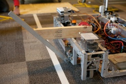
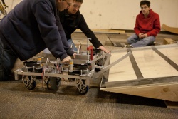
First prototype mounted on DEWBOT VII (deux) chassis for testing
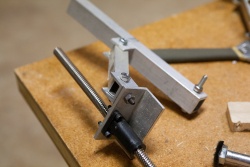
Screw deployment parts for bridge arm
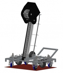
Robot CAD layout showing deployed bridge arm, chassis, lift & shooter
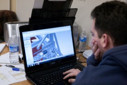
Rich Kulik designing bridge arm
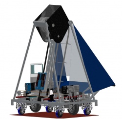
More developed CAD layout showing hopper geometry
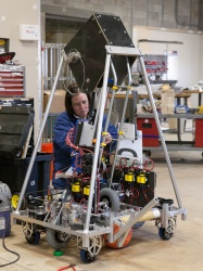
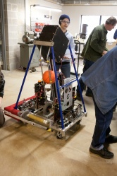
Prototype testing using DEWBOT VIII chassis


Design Details
A single window motor powered the bridge arm by turning a 1/2" diameter lead screw. Original plans to power deploy the bridge arm on both sides were abandoned due to mechanical complexity and mass constraints.
Two limit switches were employed to stop deployment either open or closed.
Prototype arm (one side only) with complete deployment mechanism showng two arms
Original bridge arm complete excluding hopper
Original bridge arm deployed at Hatboro-Horsham


Issues & Developments
While many 2012 robots successfully used an angled robot velocity driven bridge arm to manipulate the bridge, DEWBOT VIII's original bridge arm was not successful in lowering the bridge. The problem stemmed from the height of the arm's pivot point, which had to allow clearance for bridge crossing. This issue was discovered during build season and in an effort to correct this, a second arm was deployed to further depress the bridge. The angle of this second arm, however, was too steep to drive the bridge down (the robot stopped). As a result, we were not able to control the bridges at Hatboro-Horsham.
In retrospect, we always tested this bridge arm cautiously and at a quite low robot velocity. Based on observations of other robots during the 2012 season, approaching the bridge at a higher velocity (with or without the second arm) would have been likely to either succeed or result in a damaged bridge arm. This was never tried.
Gen 2 ( Lenape)
Following Hatboro-Horsham, we implimented an entirely different bridge manipulation approach. The new manupulator was an active arm driven through about 120° of arc which pushed the bridge down using the drive motor's force (in lieu of robot motion).
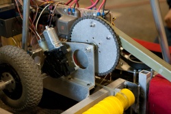
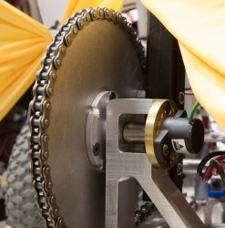
A Denso motor (Window Motor Left - 262100-3040) was used directly driving a 9T Type 35 sprocket. An axle extended from the 9T sprocket to a bearing block in the facing instrument panel, so the 9T sprocket was supported both sides. The 9T sprocket drove a 62-link type 35 chain and thereby a 54T sprocket, to which the bridge arm was attached.
The 6:1 sprocket reduction with the Denso motor provides a stall torque on the bridge arm pivot of 47 ft lbf with an unloaded rotational speed of 0.23 rev/s. With an arm length of 16.6in (pivot to bridge contact) the arm can apply a tangential force of up to 34 lbf.
The 54T sprocket and bridge arm rotated on a dead axle cantilevered from a bracket on one side. On the unsupported side, a flexible connector linked the sprocket to a Vishay 981HE0B4WA1F16 absolute encoder angle sensor. The flexible connector was originally latex tubing, but later changed to a fiberglass flexible coupling (GJ-6D from Automation Direct). The angle sensor was initially secured to the electronics panel via standoff, but later secured via a flexible polypropylene bracket connected to the bridge arm bracket.
The original bridge arm was a length of 1" x 1/8" wall square fiberglass pultrsion with a tennis ball on the end. At Lenape, this evolved to a 1¼" x 1/8" wall square 304SS square tube with 1.5 lbm of molten zinc poured into the far end and a pair of nylon wheels on the far end. The heavy steel square tube with zinc filler served as an active balancing arm, which proved quite useful at Championship. At Championship, we also introduced a new 1" x 1/8" wall steel arm equipped with a latching hook (to secure to other robots, thereby facilitating triple balancing) and nylon wheels.
This arrangement worked (sometimes), but suffered from serious reliability problems:
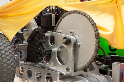
- The cantilevered arrangement of the bridge arm and sprocket assembly caused this assembly to wobble relative to the robot - a lot
- This wobble put a lot of strain on the flexible connection between the driven sprocket and the angle sensor. Sometimes the flexible connection broke. Sometimes it simply lost calibration. Occasionally the angle sensor broke. Any one of these failures rendered the bridge arm unusable and required maintenance and recalibration.
- The forces applied to the bridge arm would also occasionally bend the bridge arm bracket
At Philadelphia, these problems caused the bridge arm to be out of service in about half of our matches. At [BR]2, niether of the robots we entered into the competition had working bridge arms.
The key weaknesses were identified as:
- The bridge arm axle should be supported on both sides of the driven sprocket
- The bridge arm axle should be live and should engage the angle sensor directly
- The angle sensor mount should be part of the bridge arm axle support assembly
Original prototype mounted on Deux for testing
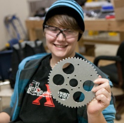
Molly with 54T sprocket
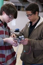
Andrew & Yahya assemble the bridge arm drive
New (fiberglass pultrusion) bridge arm on Prime
Pushing bridge up at Championship with the 304SS arm
Pushing bridge down at Championship


Gen 3 ( IRI)
Significant structural improvements were made to the bridge arm mechanism between [BR]2 and the IRI competition to addess the observed mechanical and control weaknesses.
- The bridge arm rotation shaft was supported securely on both sides
- The bridge arm rotation shaft was changed from a dead axle to a live axle - the live axle drives the angle sensor
- Polymer (Derlin) bushings replaced ball bearings
- A substantive 3/8" Al axle is employed for the rotation shaft, with an integral mount provided for the angle sensor shaft
- The new bridge arm bracket includes a secure mount for the angle sensor mounting plate
- The angle sensor mounting plate is identical in design to DEWBOT VII's - at IRI this was in fact a DEWBOT VII spare (made of polycarbonate) but this was subsequently replaced with a machined brass piece (mechanically identical) to reduce flexure
- No change to motor, chain or sprockets
- Captain Jas. Hook's bridge arm was mounted - We had, alas, no takers at IRI (cannot imagine why)
The new bracket is a substantive machined aluminum part. Before fabricating the aluminum bracket, the piece was printed using a 3D printer, assembled in place and tested. This was the team's first experience with a 3D printed part.
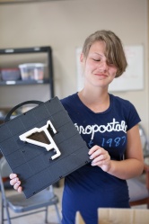
Kira with printed prototype bridge arm bracket
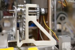
Printed prototype bridge arm bracket installed for testing on Deux
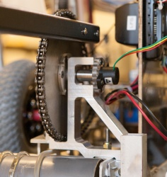
New Bridge Arm Bracket - as used at IRI - note polycarbonate sensor mount from DEWBOT VII
New Bridge Arm Bracket - sensor side view
New Bridge Arm Bracket - motor side view
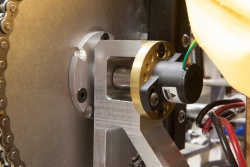
Sensor mount detail - note brass sensor mount


