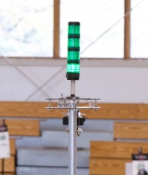
DEWBOT VII Minibot
Having a deployable Minibot was a key strategic objective from our Strategy Session. In addition:
- Minibot must remain on Post during race - MUST
- Minibot to climb post in xx sec - MUST, but xx was poorly defined during the strategy session
- Minibot must exert enough force to close switch - MUST
- Minibot should power-down and come down Post after reaching top - MUST
Contents
Early Analysis of the Minibot Problem
Email from Clem (1/24): I've adapted my 2008 robot drive-train model to the problem of FRC's 2011 MiniBot race. Model and some sample results are attached. I am not sure that all physical parameters (normal force on wheels to the pole, coefficients of friction,...) are correct. The model and results are provided as samples of what a model can provide.I used a 0.5:1 gear reduction for the sample cases. I assumed 10 lb normal force holding the minibot to the pole and high-friction wheel surfaces (probably not so realistic).
I ran the cases for 4.5, 5.0 & 5.5 lb robots. Wheel radius was varied between 1.5 and 2.3 in in 0.1 in steps.
The primary factor affecting climb time is minibot mass. No big surprise here. The lighter, the faster.
However, wheel radius (a.k.a. gear ratio) plays a significant role and there is an optimum which is a function of robot mass. Given that we have fixed gear ratios (based on the Tetrix gears), the ability to turn a custom-radius wheel could provide a useful competitive advantage. Optimizing wheel diameter/gear ratio can cut tenths of a second off the climb time.
So, to win the Minibot race:
1. Minimize Minibot mass (seconds to be saved here)
2. Deploy quickly
3. Optimize wheel diameter/gear ratio (tenths of seconds to be saved)
Regards, Clem
The effects or minibot mass and drive wheel radius was explored in detail - 31 Jan 2011, Clem
Stages of Minibot Evolution
Minibot design went through a discontinuous evolution during and after build season.
Goliath
- Our first Minibot, in large measure the child of mentor Juan Posada (with the help of others), was not formally named during its lifetime. In retrospect, the name Goliath seems appropriate.
- Goliath had front & back custom concave polycarbonate wheels (tres cool), with a bank of rare-earth magnets between them. At it's first test on 23-Jan, both motors were coupled to both wheels. The robot immediately fell off the pole when powered, leading to the white paper:
- Will my magnetic minibot fall off the pole when the power starts up? What do I do? Find out here & do the math! - 24 Jan 2011, Clem
- Will my magnetic minibot fall off the pole when the power starts up? What do I do? Find out here & do the math! - 24 Jan 2011, Clem
- Driving the front wheel only (with both motors) avoided the falling off the pole problem, but introduced wheel slippage.
- Goliath also inspired the adaptation of the robot Drive-train model to a Minibot-specific Model.
- During Goliath's development, the team developed the know-how to produce custom polycarbonate wheels (between lathe & mill).
- Mass was: can't say, Goliath is sensitive on that point. Also a little avoirdupois, Goliath did not sprint to the pole's top.
Beam-Bot
- The Beam-bot was inspired by the "fall-off-the-pole" analysis done for Goliath. It possessed one concave undriven roller at top and one driven concave wheel at bottom on opposite sides of the pole. Original prototype by Clem McKown, with subsequent development by Juan Posada and others. It was originally hoped that this design would function without needing magnets based on mass distribution and torque, but this was not the case. A tail magnet set was, alas, needed.
- Final mass = ??.
- In the end, this design was not sufficiently reliable and proposed deployment schemes were unacceptably complicated. In addition, while lighter than Goliath, it was not the lightweight minibot originally expected.
X-Bot
- A completely different approach. Pioneered by mentor David Moyer. Never optimized, but the X-bot led logically (and evolutionally) to the V-bot.
- On our 9-February Minibot Design (come to Jesus) Meeting, it was decided to pursue the unproven X-Bot concept in lieu of the Beam-Bot design under development because it was believed by the team that the X-Bot provided a more promising (simpler) deployment potential and would be more reliable in practice. During the same meeting, the transition from X-Bot to V-Bot was charted.
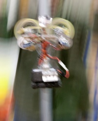
V-Bot
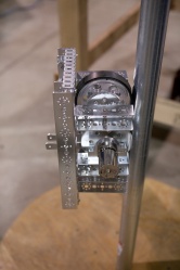
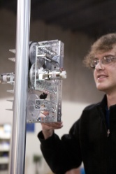
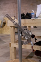
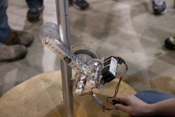
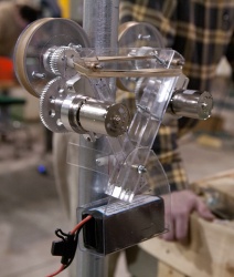
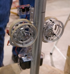
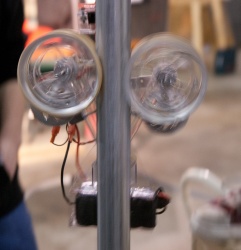
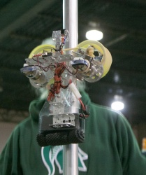
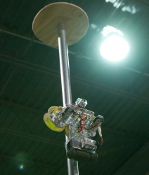
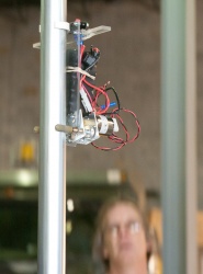
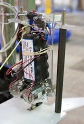
V-bot derived directly from the X-bot prototype. Like X-bot, V-bot has two arms with one motor/drivetrain each. Motors include the Tetrix gearbox and are geared 1:2 (step-up) between the gearbox and wheels.
Most of the Aluminum was replaced with polycarbonate.
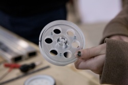
Original wheels did not grip the pole well and the robot tended to fall off. Student Molly designed new polycarbonate wheels ("Molly Wheels") which gripped the pole securely. Originally intended to use rubber band treads, these fell off easily and were replaced with large-diameter latex surgical tubing treads.
A mechanical spreader held V-Bot's arms apart prior to deployment. A pin in the center of the spreader hit the tower during deployment, forcing bach the spreader (closing the wheels on the tower) and closing a limit switch (turning on the motors).
The deployment system was designed for V-bot. V-bot was bagged with DEWBOT and participated (well, sort of) in the Finger Lakes Regional.
V-Bot's operating mass was 4.8 lbm. From start of deployment to top of pole took about 5.6 s.
During the Finger Lakes Regional we were unable to successfully launch V-Bot. The primary problem was that the normal vibrations, shake & shimmey of competition would cause the spreader holding the two arms apart to disengage, allowing the wheels to close and motors to start prematurely. Motors burned out because the release pin was still in the way, and the wheels closed on this. This is why we go to a week one competition. Back to the drawing board.
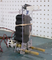
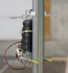
Fanger
- Fanger is a child of Gary Deaver's imagination, fueled by Chief Delphi posts (and no small amount of caffeine).
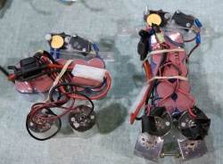
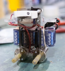
- The Tetrix motors were stripped of their gearboxes. A 2.3:1 reduction is provided to the two motors. This reduction is achieved with a latex wheel driving an aluminum wheel and slippage at this point should the minibot stall prevents motor burn-out. Each motor drives one long, 3/8" OD wheel. The "wheels" give the minibot its name, since these bear more than a passing resemblance to snake fangs.
- Everything is minimalized to keep mass to the lowest level practical. Current mass is 2.6 lbm. Time to the top of the pole is about 1.7 seconds. Adding deployment time brings this to 3.3 s.
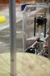
- The pneumatic launch platform was modified to launch Fanger. Pulling a "hand grenade" pin activates the motor during deployment.
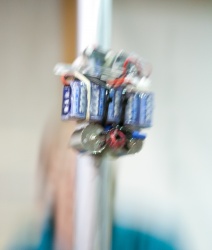
- Fanger performed very well and reliably in Philadelphia qualification matches, raising us approximately 17 seeds. We could not have won without it! Unfortunately, the rough & tumble of elimination matches proved too much for Fanger until last-minute braces kept to from shaking off its stand.
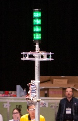
Fanger winning the minibot race during Philadelphia qualifications
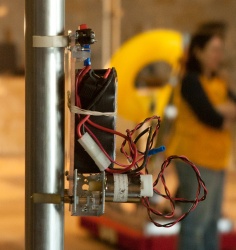
Mighty Mouse
- Fanger performed wonderfully at Philadelphia, but it was far from the fastest Minibot on the field. During 1640's Philadelphia Post-Mortem, the team identified a world-class Minibot as an important objective for the Championship. This Mission (Mighty Mouse) was entrusted to Gary Deaver.
- Mightly Mouse is lighter than Fanger at 2.1 lbm. "Wheels" are again 3/8" OD latex tubing and are directly-driven from the gearboxless Tetrix motors.
- Time trials at DRC indicate that time from start of deployment to top of pole is under 1.5 s. This is shorter than either deployment time or climb time at Philadelphia! We have a contender.
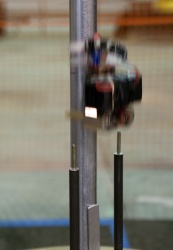
- Mouse made its debut at Championship with excellent results. Reliability was 100% (All purposful deployments resulted in a completed minibot race) with Mighty Mouse placing either 1st or 2nd in its races.
The moment of contact - Mighty Mouse wins again at Duel on the Delaware
