Difference between revisions of "DEWBOT XII Drive-Train"
MaiKangWei (talk | contribs) |
MaiKangWei (talk | contribs) (→Photographs) |
||
| (48 intermediate revisions by the same user not shown) | |||
| Line 1: | Line 1: | ||
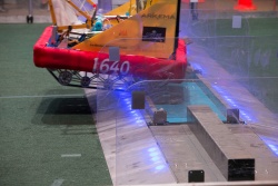
| − | After six years of successful [[Swerve Central | Swerve Drive]] development, along comes FIRST Stronghold. Our first conclusion concerning the game: it's not a swerve game. The outerworks obstacles require a different approach. | + | [[Image:HH_160305-43.jpg|350px|right|thumb|Crossing the Rock Wall at [[DEWBOT XII Hatboro-Horsham | Hatboro-Horsham]]]]After six years of successful [[Swerve Central | Swerve Drive]] development, along comes FIRST Stronghold. Our first conclusion concerning the game: it's not a swerve game. The outerworks obstacles require a different approach. |
Three approaches were explored: | Three approaches were explored: | ||
| Line 6: | Line 6: | ||
#treaded tank drive | #treaded tank drive | ||
| − | Of these, the first and last were tested; the bogie suspension was not tested because it seemed to be more suited to low velocity than high. | + | Of these, the first and last were tested; the bogie suspension was not tested because it seemed to be more suited to low velocity travel than high. |
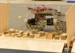
| − | An 8-wheel tank chassis was built using 8" AndyMark pneumatic wheels. All wheels were driven. This chassis was able to cross b & d obstacles, but bounced excessively in the process. The crossings were not under control. The moat crossing was especially troublesome. | + | An 8-wheel prototype tank chassis was built and tested using 8" AndyMark pneumatic wheels. All wheels were driven. This chassis was able to cross b & d obstacles, but bounced excessively in the process. The crossings were not under control. The moat crossing was especially troublesome. |
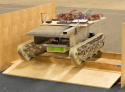
| − | Treaded tank drive was able to cross all b & d. | + | Treaded tank drive was able to cross all type b & d obstacles while retaining good control. An attribute of tracked vehicles is that they have better mobility than pneumatic tires over rough terrain. They smooth out the bumps, glide over small obstacles and are capable of crossing breaks in the terrain. This is why military tanks use treads. |
| + | |||
| + | ==Drive-train Objectives== | ||
| + | *Facilitate reliable and rapid crossing all b & d type outerworks obstacles in either autonomous or teleop control; | ||
| + | *Non-interference with crossing types a & c outerworks obstacles; | ||
| + | *Speed consistent with game needs (~12 ft/s) while retaining fine control | ||
| + | *Turns quickly and easily - without requiring excessive motor power or creating large hysteresis; | ||
| + | *Not sensitive to T-bone attack | ||
| + | *Reliable & easily serviceable | ||
| + | |||
| + | ==Drivetrain Specifications== | ||
| + | *~12 ft/s maximum speed | ||
| + | *Able to climb 4-5/8" steel steps | ||
| + | *A minimum of 3in ground clearance between tracks to avoid fouling on Ramparts or Rough Terrain | ||
| + | *In absence of shooter turret, must be able to accurately rotate robot in-place with ±1º accuracy (needed to consistently score in high goal off-axis from the outer-works) | ||
| + | *Bi-directional: crosses type b & d obstacles (approximately) equally well driving either forwards or backwards | ||
| + | *Modular drive-train enabling rapid replacement | ||
| + | |||
| + | ==Design Inspiration== | ||
| + | Sam Shawe-Owner-President of Outback Mfg (63076 Crusher Ave, Bend Or 97701 - www.outbackmfg.com - sam@outbackmfg.com) had designed FRC chasses around Brecoflex belts and pulleys for previous years' FRC games. Posted video of these chasses demonstrated that they managed FIRST Stronghold defenses well. Sam Shawe graciously shared these CAD designs with us. | ||
| + | |||
| + | <gallery widths=250 heights=250 perrow=3> | ||
| + | Image:track2.jpg|Early Shawe design | ||
| + | Image:track3.jpg|Later (developed) Shawe design | ||
| + | Image:track4.jpg| | ||
| + | </gallery> | ||
| + | |||
| + | Sam Shawe's designs provided inspiration and a starting point, but we designed [[DEWBOT XII]]'s tracked drive system from our objectives and specifications. | ||
| + | |||
| + | ==Design Considerations== | ||
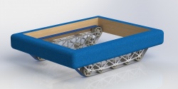
| + | [[image:Track 160124a.jpg|300px|right|thumb|Rendered drive module (x-track)]]As with the Shawe chasses, DEWBOT XII's drive-train is based on a pair of Brecoflex 50mm wide TK10K13 steel-belted polyurethane timing belts. This belt design possesses a central raised guide which prevents belt shift left-right. This guide indexes into grooves in the drive-train pulleys and idlers. This belt has a 10mm pitch and may be ordered in any length at 10mm increments. Brecoflex provides FRC teams with a [[media:Brecoflex_FIRST_Robotics_Design_Guide.pdf | design guide]]. | ||
| + | |||
| + | Due to concern that a high-traction track would make steering difficult and leave the robot subject to T-bone attack, one of the belt surfaces selected for testing was the medium-traction, abrasion-resistant T-cover surface. Following testing, this medium-traction belt was selected for the robot. The belt/T-cover combination has a minimum pulley diameter of 80mm. To prevent the edge of the belt from digging into the field carpet, the belt edges were milled to a 45<sup>o</sup> miter. | ||
| + | |||
| + | A 30-tooth drive pulley (Brecoflex AL55TK10K13 30-0) was selected based on the belt's 80mm minimum pulley diameter. The pitch diameter of the 30-tooth pulley is (30 teeth x 10mm pitch / π =) 95.5mm (3.76 in). From the standpoint of speed and gear reduction calculation, the pitch diameter is effectively the wheel diameter. | ||
| + | |||
| + | To climb a 4-5/8" step, the front pulley/idler must be mounted above and in front of the first road wheel, so that the belt forms an angle enabling the climb. A 45<sup>o</sup> angle was used and, because we wanted to cross obstacles bidirectionally, this was applied symmetrically to the drive-train's front and back. | ||
| + | |||
| + | [[image:DB12_160213-7.jpg|300px|right|thumb|Drive detail showing drive pulley, large and small road wheels (idlers)]]Placing angled belts on both front and rear limits the wheelbase. A 33.75 long x 25.75 inch wide chassis perimeter was employed to provide adequate wheelbase for stability in crossing obstacles. With this chassis length, a 22.691 inch effective wheelbase is achieved. This wheelbase is supported by five, idle road wheels. The first and last of these road wheels are 3.42 inch diameter providing the same pitch diameter as the drive pulley. The first and last road wheels are elevated 1/8" vis-à-vis the center three to provide easier turning without significantly impacting stability. The center three road wheels are 2.465 inch diameter, level and span the center 12 inches of wheelbase. A sixth, high idle wheel provided for belt return in opposition to the drive pulley. Belt length is 1870mm (Brecoflex 50 TK10K13/1870 V T PAZ). | ||
| + | |||
| + | All six idlers were machined from cast nylon and possessed grooves to accommodate the TK10K13 belt's guide. All were fitted with pressed ball bearing races and mounted on steel dead axles; 1/2" OD axles for the large idlers and 3/8" axles for the small (center road wheel) idlers. The six dead idler axles also served as structural elements. | ||
| + | |||
| + | Pulley and idlers were supported between two highly-relieved 1/4" 6061 Al Trackway Plates. The interior Trackway Plate also mounted the Powerplant. The Interior and Exterior Trackway Plates were joined by the six above-mentioned idler axles, four (later 5) spacers with through bolts, and two 3/8" thick 6061 Al Mounting Plates. Mounted on the chassis, the outside face of the Exterior Trackway Plate is positioned at the chassis perimeter. | ||
| + | |||
| + | Each drive assembly mounted to the chassis via (4) 1/4"-20 x 1.75" SHCSs through holes in the Mounting Plates. Left and right drive assemblies are mirrored (not identical). Each drive assembly, including powerplant and track, weighs 15.0 lb<sub>m</sub>. | ||
| + | |||
| + | ==Powerplant== | ||
| + | Each drive assembly is powered by two (2) CIM motors through a single-speed double-reduction VexPro gearbox ([http://www.vexrobotics.com/vexpro/motion/gearboxes/single-speed-double-reduction.html VexPro 217-2454]). This gearbox comes with a 40:12 first stage reduction and 40:14 second stage (yielding 9.52:1 overall reduction). We replaced the 40:14 second stage gears with a 36:18 combination (VexPro 217-3214 & 217-3208, respectively) to create a gearbox having 6.67:1 overall reduction in order to meet speed specification we had set. | ||
| + | |||
| + | The gearboxes' 1/2" hex output shafts were modified by: | ||
| + | # cutting to length; and | ||
| + | # turning the shaft end down to 1/2" round to accommodate a standard 1/2" flanged bearing. | ||
| + | |||
| + | The team's initial experience using a 1/2" hex flanged bearing to support the output shaft end demonstrated that these hex bearings were weak and that the inner ring tended to fracture at the hex points leading to bearing and drive-train failure. These bearing failures were eliminated by switching to 1/2" standard round bearings. | ||
| + | |||
| + | A quadrature encoder was mounted on the opposing end of the gearbox output shaft. | ||
| + | |||
| + | ==Drawings== | ||
| + | <gallery widths=250 heights=250 perrow=3> | ||
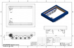
| + | Image:track_160124a.jpg|Rendered track drive unit | ||
| + | Image:track_160124c.jpg|Rendered track drives w/ simple bumper | ||
| + | Image:chassis_work.jpg|Start of chassis design ([[media:chassis_work.pdf | pdf]]) | ||
| + | Image:drive_right.jpg|Right side tracked drive assembly ([[media:drive_right.pdf | pdf]]) | ||
| + | Image:al55tk10k13_30-0.jpg|track drive sprocket ([[media:al55tk10k13_30-0.pdf | pdf]]) | ||
| + | Image:idler-large.jpg|Large track idler pulley ([[media:idler-large.pdf | pdf]]) | ||
| + | Image:idler-small.jpg|Small track idler pulley ([[media:idler-small.pdf | pdf]]) | ||
| + | Image:trackway_pattern_inside.jpg|Trackway interior plate ([[media:trackway_pattern_inside.pdf | pdf]]) | ||
| + | Image:trackway_pattern_outside.jpg|Trackway exterior plate ([[media:trackway_pattern_outside.pdf | pdf]]) | ||
| + | </gallery> | ||
| + | |||
| + | ==Experience & Post-Design Modifications== | ||
| + | The hex-bearing issue has been discussed in the Powerplant section. | ||
| + | |||
| + | A weakness exists in the connection between the Trackway Plates at the drive axle, allowing the drive shaft end to disengage from the bearing in the exterior Trackway Plate. This was largely corrected by adding a 5<sup>th</sup> spacer/through-bolt unit at the top of the Trackway Plates near the drive axle. | ||
| + | |||
| + | General drive-train performance was very good. Reliability was outstanding. The outer-works obstacles made this a very abusive game for robot drive-trains and Sab-BOT-age's drive-train weathered this abuse with almost no maintenance or repairs. | ||
| + | |||
| + | The follow issues were noted: | ||
| + | # The '''Moat''' is dangerous in that if we end up turned sideways with one track between the two raised beams, DEWBOT XII cannot escape. Period. This occurred four times during the FRC competition season. Appropriate driver action can prevent this but a high level of driver skill, training and discipline is needed to avoid such entrapment. On the surface, the Rock Wall seems to present the identical danger, but we have never become trapped on the Rock Wall (but came close on one occasion - saved by driver action). | ||
| + | # The '''Ramparts''' are more difficult to cross than expected. To cross, DEWBOT XII should run backwards (light end forward) and full drive power needs to be applied at the instant that the track hits the Rampart step. When we do this, we are successful. Otherwise, we get turned sideways. Unlike the Moat, we can easily escape such a turn. DEWBOT XII has never crossed the Ramparts in Autonomous (we never tried). | ||
| + | # '''Rough Terrain''' is generally no problem other than it is too easy and in Autonomous we often go too far and can miss our Autonomous shot. Rough Terrain sometimes turns DEWBOT XII (for the same reason as Ramparts), but generally not and this is always recoverable in Teleop. If the Rough Terrain in in place in lieu of the Rock Wall, this is DEWBOT XII's crossing of choice. | ||
| + | # '''Rock Wall''' is by far the easiest and fastest obstacle for DEWBOT XII to cross, and is our crossing of choice (both Autonomous & Teleop). We generally cross forward (heavy end forward). With the lift winch and scaling equipment mounted, DEWBOT XII ''must'' cross the Rock Wall forward. | ||
| + | # On one occasion, a successful '''T-Bone attack''' was carried out on DEWBOT XII (in a Westtown Qual Match). Appropriate driver action was identified to counteract such attacks. | ||
| + | # On one occasion (MAR Championship), damaged CIM power wires were discovered on one CIM drive motor. This seems to be the result of a discrete event (e.g. pinching the wires during a drive assembly mounting). Both wires on the affected CIM were damaged (insulation was compromised) at a similar distance from the CIM motor. There was no obvious wear mechanism which could have caused this damage. The damaged CIM was discarded and replaced. | ||
| + | |||
| + | ==New Manufacturing Techniques== | ||
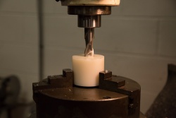
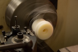
| + | *''Milling with turntable'' - We borrowed a turntable to mount on the mill and used this to machine the idler wheels and drive pulley. | ||
| + | *''Hex Broach'' - The drive pulleys were purchased with plain 12mm holes. We needed 1/2" hex holes to mate with the gearbox output shafts. We purchased a hex broach and used the arbor press to broach these hex holes (after drilling to 1/2" in lathe). | ||
| + | *''Water-Jet Milling'' - The Trackway plates were the first parts we've ever designed from the start to be Water-Jet milled. A local shop did the actual Water-Jet cutting. | ||
| + | |||
| + | ==Photographs== | ||
| + | <gallery widths=250 heights=250 perrow=3> | ||
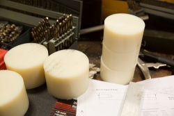
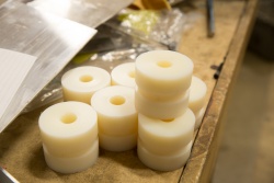
| + | Image:DB12_160126-5.jpg|Nylon for idler pulleys | ||
| + | Image:DB12_160127-2.jpg|Brecoflex [http://www.brecoflex.com/index.php?CATID=1&SCATID=2&SMENID=11&PURA=21 AL55tk10k13] 30-tooth pulley w/ 12mm plain hub (as-received) | ||
| + | Image:DB12_160127-3.jpg|Smooth polyurethane-finish TK10K13 belts (1870mm) | ||
| + | Image:DB12_160129-1.jpg|Water jetted drive side plates | ||
| + | Image:DB12_160129-2.jpg|Andrew with (outer) side plate | ||
| + | Image:DB12_160130-13.jpg|Milling bearing recess using turntable | ||
| + | Image:DB12_160130-14.jpg|Partially assembled drive modules | ||
| + | Image:DB12_160130-15.jpg|Cutting pulley groove | ||
| + | image:DB12_160131-1.jpg|Pulley & hexagonal broach just barely fit in our Arbor Press | ||
| + | image:DB12_160131-3.jpg|The team's first hexagonal hole ever "drilled" | ||
| + | image:DB12_160131-4.jpg|Small idler pulley | ||
| + | image:DB12_160131-7.jpg|Small idler pulley with bearings & shaft | ||
| + | image:DB12_160131-13.jpg|Drive train module | ||
| + | image:DB12_160202-5.jpg| | ||
| + | image:DB12_160204-1.jpg|Adding weight for realistic driving | ||
| + | image:DB12_160204-8.jpg|Crossing the rampart | ||
| + | image:DB12_160204-9.jpg|Crossing rough terrain | ||
| + | image:DB12_160204-10.jpg|Crossing the moat | ||
| + | image:DB12_160204-11.jpg|Crossing the rock wall | ||
| + | image:DB12_160204-15.jpg|Crossing rampart | ||
| + | image:DB12_160204-16.jpg|Crossing rough terrain | ||
| + | image:DB12_160204-17.jpg|Crossing moat | ||
| + | image:DB12_160205-2.jpg|Rough cut and faced large idler pulleys | ||
| + | image:DB12_160205-1.jpg|Turned and grooved small idler pulleys | ||
| + | image:DB12_160206-1.jpg|Large idler pulley prior to drilling revolver holes | ||
| + | image:DB12_160206-2.jpg|Ready to drill revolver holes | ||
| + | image:DB12_160206-5.jpg|Finished large idler pulley | ||
| + | image:DB12_160206-10.jpg|Idler pulleys | ||
| + | image:DB12_160206-16.jpg|Drive pulleys in process | ||
| + | image:DB12_160206-17.jpg|Drive pulley | ||
| + | image:DB12_160206-18.jpg|Paul | ||
| + | image:DB12_160207-2.jpg|Gearbox w/ end of hex shaft turned down to round to accommodate a round bearing (stronger than a hex bearing) | ||
| + | image:DB12_160207-3.jpg|Machined pulley mounted | ||
| + | image:DB12_160208-9.jpg|Fully machined drive pulleys | ||
| + | image:DB12_160213-6.jpg|Chassis (deux's) and drive (prime's) | ||
| + | image:DB12_160213-8.jpg|Drive detail showing drive pulley and gearbox mount | ||
| + | image:DB12_160213-9.jpg|Drive detail showing chamfering on belt | ||
| + | image:DB12_160218-8.jpg|Eric, Dana, Laura & Alicia install the drive modules on ''prime'' | ||
| + | image:DB12_160219-1.jpg|Additional spacer added to ''prime'' to prevent bearing loss at driveshaft end | ||
| + | image:DB12_160220-5.jpg| | ||
| + | image:DB12_160223-28.jpg| | ||
| + | Image:HH_160305-43.jpg|Rock Wall at Hatboro-Horsham | ||
| + | Image:HH_160305-60.jpg|Rough Terrain at Hatboro-Horsham | ||
| + | Image:DB12_Seneca_160319-35.jpg|Moat at Seneca | ||
| + | Image:DB12_FRC_Champs_160428-20.jpg|Moat on Newton | ||
| + | </gallery> | ||
---- | ---- | ||
| − | [[Category:Robot]][[Category:DEWBOT XII]][[Category:Drive-train]] | + | [[Category:Robot]][[Category:DEWBOT XII]][[Category:Photo Galleries]][[Category:Drive-train]][[Category:Engineering]] |
Latest revision as of 22:57, 13 May 2016

Three approaches were explored:
- 6 or 8 wheel tank drive using 8" (or larger) pneumatic wheels;
- 6-wheel tank drive with a bogie suspension
- treaded tank drive
Of these, the first and last were tested; the bogie suspension was not tested because it seemed to be more suited to low velocity travel than high.
An 8-wheel prototype tank chassis was built and tested using 8" AndyMark pneumatic wheels. All wheels were driven. This chassis was able to cross b & d obstacles, but bounced excessively in the process. The crossings were not under control. The moat crossing was especially troublesome.
Treaded tank drive was able to cross all type b & d obstacles while retaining good control. An attribute of tracked vehicles is that they have better mobility than pneumatic tires over rough terrain. They smooth out the bumps, glide over small obstacles and are capable of crossing breaks in the terrain. This is why military tanks use treads.
Contents
Drive-train Objectives
- Facilitate reliable and rapid crossing all b & d type outerworks obstacles in either autonomous or teleop control;
- Non-interference with crossing types a & c outerworks obstacles;
- Speed consistent with game needs (~12 ft/s) while retaining fine control
- Turns quickly and easily - without requiring excessive motor power or creating large hysteresis;
- Not sensitive to T-bone attack
- Reliable & easily serviceable
Drivetrain Specifications
- ~12 ft/s maximum speed
- Able to climb 4-5/8" steel steps
- A minimum of 3in ground clearance between tracks to avoid fouling on Ramparts or Rough Terrain
- In absence of shooter turret, must be able to accurately rotate robot in-place with ±1º accuracy (needed to consistently score in high goal off-axis from the outer-works)
- Bi-directional: crosses type b & d obstacles (approximately) equally well driving either forwards or backwards
- Modular drive-train enabling rapid replacement
Design Inspiration
Sam Shawe-Owner-President of Outback Mfg (63076 Crusher Ave, Bend Or 97701 - www.outbackmfg.com - sam@outbackmfg.com) had designed FRC chasses around Brecoflex belts and pulleys for previous years' FRC games. Posted video of these chasses demonstrated that they managed FIRST Stronghold defenses well. Sam Shawe graciously shared these CAD designs with us.
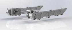
Early Shawe design
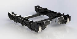
Later (developed) Shawe design
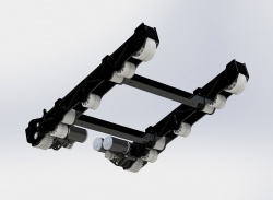


Sam Shawe's designs provided inspiration and a starting point, but we designed DEWBOT XII's tracked drive system from our objectives and specifications.
Design Considerations
As with the Shawe chasses, DEWBOT XII's drive-train is based on a pair of Brecoflex 50mm wide TK10K13 steel-belted polyurethane timing belts. This belt design possesses a central raised guide which prevents belt shift left-right. This guide indexes into grooves in the drive-train pulleys and idlers. This belt has a 10mm pitch and may be ordered in any length at 10mm increments. Brecoflex provides FRC teams with a design guide.
Due to concern that a high-traction track would make steering difficult and leave the robot subject to T-bone attack, one of the belt surfaces selected for testing was the medium-traction, abrasion-resistant T-cover surface. Following testing, this medium-traction belt was selected for the robot. The belt/T-cover combination has a minimum pulley diameter of 80mm. To prevent the edge of the belt from digging into the field carpet, the belt edges were milled to a 45o miter.
A 30-tooth drive pulley (Brecoflex AL55TK10K13 30-0) was selected based on the belt's 80mm minimum pulley diameter. The pitch diameter of the 30-tooth pulley is (30 teeth x 10mm pitch / π =) 95.5mm (3.76 in). From the standpoint of speed and gear reduction calculation, the pitch diameter is effectively the wheel diameter.
To climb a 4-5/8" step, the front pulley/idler must be mounted above and in front of the first road wheel, so that the belt forms an angle enabling the climb. A 45o angle was used and, because we wanted to cross obstacles bidirectionally, this was applied symmetrically to the drive-train's front and back.
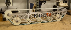
Placing angled belts on both front and rear limits the wheelbase. A 33.75 long x 25.75 inch wide chassis perimeter was employed to provide adequate wheelbase for stability in crossing obstacles. With this chassis length, a 22.691 inch effective wheelbase is achieved. This wheelbase is supported by five, idle road wheels. The first and last of these road wheels are 3.42 inch diameter providing the same pitch diameter as the drive pulley. The first and last road wheels are elevated 1/8" vis-à-vis the center three to provide easier turning without significantly impacting stability. The center three road wheels are 2.465 inch diameter, level and span the center 12 inches of wheelbase. A sixth, high idle wheel provided for belt return in opposition to the drive pulley. Belt length is 1870mm (Brecoflex 50 TK10K13/1870 V T PAZ).
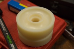
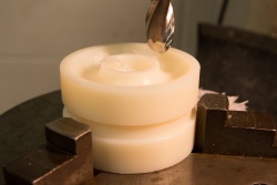
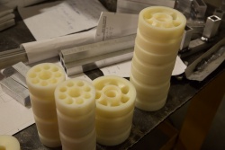
All six idlers were machined from cast nylon and possessed grooves to accommodate the TK10K13 belt's guide. All were fitted with pressed ball bearing races and mounted on steel dead axles; 1/2" OD axles for the large idlers and 3/8" axles for the small (center road wheel) idlers. The six dead idler axles also served as structural elements.
Pulley and idlers were supported between two highly-relieved 1/4" 6061 Al Trackway Plates. The interior Trackway Plate also mounted the Powerplant. The Interior and Exterior Trackway Plates were joined by the six above-mentioned idler axles, four (later 5) spacers with through bolts, and two 3/8" thick 6061 Al Mounting Plates. Mounted on the chassis, the outside face of the Exterior Trackway Plate is positioned at the chassis perimeter.
Each drive assembly mounted to the chassis via (4) 1/4"-20 x 1.75" SHCSs through holes in the Mounting Plates. Left and right drive assemblies are mirrored (not identical). Each drive assembly, including powerplant and track, weighs 15.0 lbm.
Powerplant
Each drive assembly is powered by two (2) CIM motors through a single-speed double-reduction VexPro gearbox (VexPro 217-2454). This gearbox comes with a 40:12 first stage reduction and 40:14 second stage (yielding 9.52:1 overall reduction). We replaced the 40:14 second stage gears with a 36:18 combination (VexPro 217-3214 & 217-3208, respectively) to create a gearbox having 6.67:1 overall reduction in order to meet speed specification we had set.
The gearboxes' 1/2" hex output shafts were modified by:
- cutting to length; and
- turning the shaft end down to 1/2" round to accommodate a standard 1/2" flanged bearing.
The team's initial experience using a 1/2" hex flanged bearing to support the output shaft end demonstrated that these hex bearings were weak and that the inner ring tended to fracture at the hex points leading to bearing and drive-train failure. These bearing failures were eliminated by switching to 1/2" standard round bearings.
A quadrature encoder was mounted on the opposing end of the gearbox output shaft.
Drawings
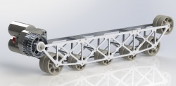
Rendered track drive unit
Rendered track drives w/ simple bumper
Start of chassis design ( pdf)
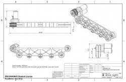
Right side tracked drive assembly ( pdf)
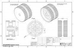
track drive sprocket ( pdf)
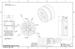
Large track idler pulley ( pdf)
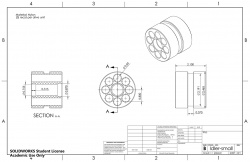
Small track idler pulley ( pdf)
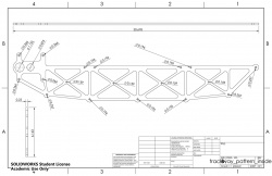
Trackway interior plate ( pdf)
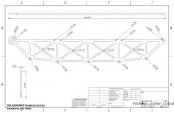
Trackway exterior plate ( pdf)


Experience & Post-Design Modifications
The hex-bearing issue has been discussed in the Powerplant section.
A weakness exists in the connection between the Trackway Plates at the drive axle, allowing the drive shaft end to disengage from the bearing in the exterior Trackway Plate. This was largely corrected by adding a 5th spacer/through-bolt unit at the top of the Trackway Plates near the drive axle.
General drive-train performance was very good. Reliability was outstanding. The outer-works obstacles made this a very abusive game for robot drive-trains and Sab-BOT-age's drive-train weathered this abuse with almost no maintenance or repairs.
The follow issues were noted:
- The Moat is dangerous in that if we end up turned sideways with one track between the two raised beams, DEWBOT XII cannot escape. Period. This occurred four times during the FRC competition season. Appropriate driver action can prevent this but a high level of driver skill, training and discipline is needed to avoid such entrapment. On the surface, the Rock Wall seems to present the identical danger, but we have never become trapped on the Rock Wall (but came close on one occasion - saved by driver action).
- The Ramparts are more difficult to cross than expected. To cross, DEWBOT XII should run backwards (light end forward) and full drive power needs to be applied at the instant that the track hits the Rampart step. When we do this, we are successful. Otherwise, we get turned sideways. Unlike the Moat, we can easily escape such a turn. DEWBOT XII has never crossed the Ramparts in Autonomous (we never tried).
- Rough Terrain is generally no problem other than it is too easy and in Autonomous we often go too far and can miss our Autonomous shot. Rough Terrain sometimes turns DEWBOT XII (for the same reason as Ramparts), but generally not and this is always recoverable in Teleop. If the Rough Terrain in in place in lieu of the Rock Wall, this is DEWBOT XII's crossing of choice.
- Rock Wall is by far the easiest and fastest obstacle for DEWBOT XII to cross, and is our crossing of choice (both Autonomous & Teleop). We generally cross forward (heavy end forward). With the lift winch and scaling equipment mounted, DEWBOT XII must cross the Rock Wall forward.
- On one occasion, a successful T-Bone attack was carried out on DEWBOT XII (in a Westtown Qual Match). Appropriate driver action was identified to counteract such attacks.
- On one occasion (MAR Championship), damaged CIM power wires were discovered on one CIM drive motor. This seems to be the result of a discrete event (e.g. pinching the wires during a drive assembly mounting). Both wires on the affected CIM were damaged (insulation was compromised) at a similar distance from the CIM motor. There was no obvious wear mechanism which could have caused this damage. The damaged CIM was discarded and replaced.
New Manufacturing Techniques
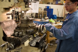
- Milling with turntable - We borrowed a turntable to mount on the mill and used this to machine the idler wheels and drive pulley.
- Hex Broach - The drive pulleys were purchased with plain 12mm holes. We needed 1/2" hex holes to mate with the gearbox output shafts. We purchased a hex broach and used the arbor press to broach these hex holes (after drilling to 1/2" in lathe).
- Water-Jet Milling - The Trackway plates were the first parts we've ever designed from the start to be Water-Jet milled. A local shop did the actual Water-Jet cutting.
Photographs
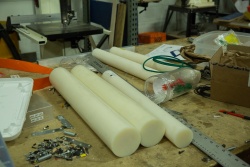
Nylon for idler pulleys
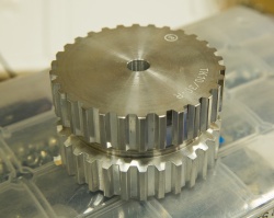
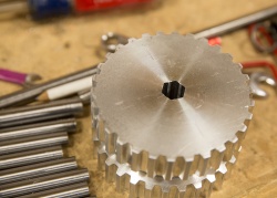
Brecoflex AL55tk10k13 30-tooth pulley w/ 12mm plain hub (as-received)
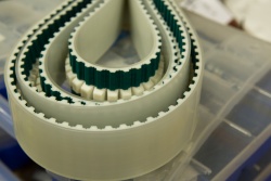
Smooth polyurethane-finish TK10K13 belts (1870mm)
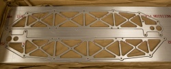
Water jetted drive side plates
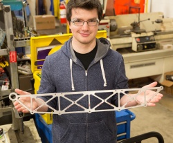
Andrew with (outer) side plate
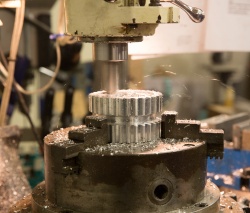
Milling bearing recess using turntable
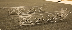
Partially assembled drive modules
Cutting pulley groove
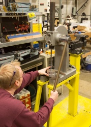
Pulley & hexagonal broach just barely fit in our Arbor Press
The team's first hexagonal hole ever "drilled"
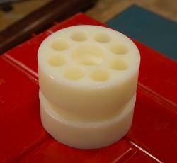
Small idler pulley
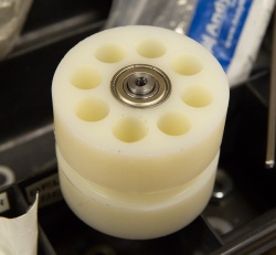
Small idler pulley with bearings & shaft
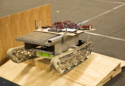
Drive train module
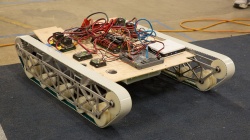
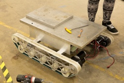
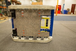
Adding weight for realistic driving
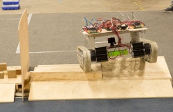
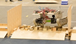
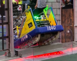
Crossing the rampart
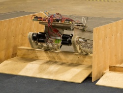
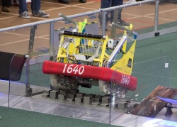
Crossing rough terrain
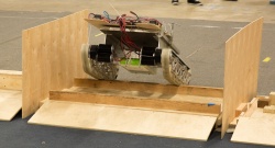
Crossing the moat
Crossing the rock wall
Crossing rampart
Crossing rough terrain
Crossing moat
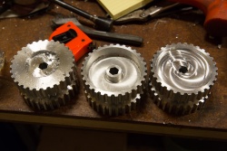
Rough cut and faced large idler pulleys
Turned and grooved small idler pulleys
Large idler pulley prior to drilling revolver holes
Ready to drill revolver holes
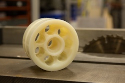
Finished large idler pulley
Idler pulleys
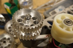
Drive pulleys in process
Drive pulley
Paul
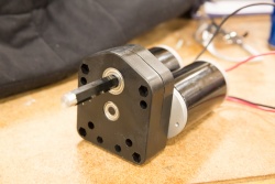
Gearbox w/ end of hex shaft turned down to round to accommodate a round bearing (stronger than a hex bearing)
Machined pulley mounted
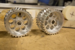
Fully machined drive pulleys
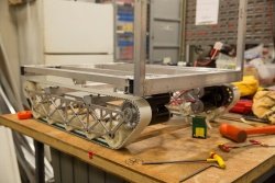
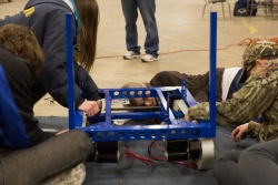
Chassis (deux's) and drive (prime's)
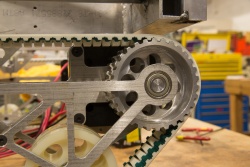
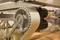
Drive detail showing drive pulley and gearbox mount
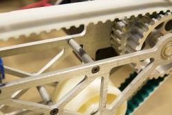
Drive detail showing chamfering on belt
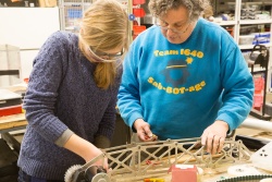
Eric, Dana, Laura & Alicia install the drive modules on prime
Additional spacer added to prime to prevent bearing loss at driveshaft end
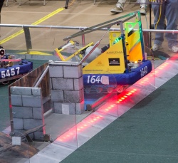
Rock Wall at Hatboro-Horsham
Rough Terrain at Hatboro-Horsham
Moat at Seneca
Moat on Newton


