Difference between revisions of "Talk:DEWBOT X Midknight Mayhem"
MaiKangWei (talk | contribs) (→Results of Velocity Testing) |
MaiKangWei (talk | contribs) (→Results of Velocity Testing) |
||
| Line 35: | Line 35: | ||
==Results of Velocity Testing== | ==Results of Velocity Testing== | ||
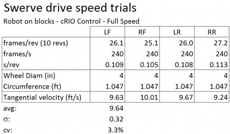
| − | [[image:Swerve_speed_blocks_cRIO.jpg|450px|right]]Initial tests were conducted with the robot on blocks and controlled with the cRIO. All systems operated simultaneously. | + | [[image:Swerve_speed_blocks_cRIO.jpg|450px|right]]Initial tests were conducted with the robot on blocks and controlled with the cRIO. All systems operated simultaneously. The slingshot was held in tension during these tests, but the compressor was not running (because the storage air pressure was at target level). Wheels drives were run at full speed. |
| + | |||
| + | Average maximum wheel speed was measured at 9.64 ft/s. This is close to the original Drive-train model predictions (9.77 ft/s). | ||
| + | |||
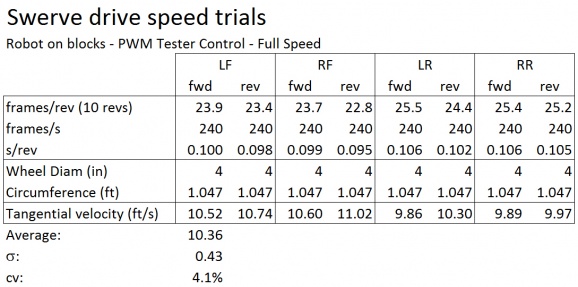
| + | [[image:Swerve_speed_blocks_PWM.jpg|578px|right]]Velocity was significantly higher when wheels were driven individually with the PWM tester. While not certain (and no relevant data was collected to resolve this), it is likely that the higher velocity reflects higher battery voltage available when running only one CIM on blocks as opposed to running four CIMS (on blocks) while also powering the rest of the robot's systems (save compressor, which was off). | ||
---- | ---- | ||
[[Category:DEWBOT X]][[Category:Engineering]][[Category:Drive-train]][[Category:Pivot Drive]] | [[Category:DEWBOT X]][[Category:Engineering]][[Category:Drive-train]][[Category:Pivot Drive]] | ||
Revision as of 10:18, 4 July 2014
During the mentors' matches, Douglas noticed that the drive train was not working correctly. He suspected a pivot out of calibration. Robot would not drive straight.
We checked this back in the pit and what we observed was:
- The wheel treads on the robot's left side are completely worn. The right side treads are not nearly so worn (both were changed at the same time: at FRC Championships)
- In crab drive, everything looks normal. Left front wheel starts driving a bit later than the rest, but angles and drive directions look okay.
- In ocelot, we some drive angles that don't seem to make any sense.
The differential wear suggests we have wheels fighting each other as we drive, most likely due to incorrect angle. This would also explain the not driving straight complaint.
This could also tie into the low drive speed issue. We need more data.
Contents
Drive Speed Issue
Which checking drive speed with video on 14-June, I discovered that DEWBOT X's top speed was no more than 6 ft/s (avg = 5.6 ft/s; std dev = 0.5 ft/s; n = 9). It should be about 9 ft/s.
If drive-train frictional forces were causing this speed reduction, each of our CIMS would be drawing about 60 amps and the 40 amp breakers (not to mention the 100 amp main breaker) would be tripping constantly. They are not.
Action List for 2-July meeting
- Video each pivot wheel for speed determination at 120 or 240 fps (Use GoPro Black) - determine rotational speed for each wheel for each test
- Robot on blocks - driven by on-board control at top speed
- Robot on blocks - driven by PWM tester at top speed
- Robot driving straight ahead top speed (joystick straight ahead w/out correction)
- Robot driving straight ahead top speed (correcting to maintain course)
- With robot on back, simultaneously video robot bottom and x-box controller to have linked video of control input and wheel angle output - high quality video needed here - 30 or 60 fps 1080p
- Video each pivot wheel for speed determination at 120 or 240 fps (Use GoPro Black) - determine rotational speed for each wheel for each test
Velocity testing Procedure
Wheel velocity was measured for each wheel on Prime using a GoPro Hero 3 (or Hero 3+) Black shooting WVGA at 240 fps. Wheel rims were marked to facilitate revolution count. Video frames per wheel revolution were counted to determine velocity. All four wheels were tested and are identified using cardinal directions: Left Front (LF); Right Front (RF); Left Rear (LR); and Right Rear (RR).
In stationary tests with the robot on blocks, video frames for ten revolutions were counted. By using 10 revolutions, the systematic precision of the velocity measurements was on the order of 0.05 ft/s (varying with velocity measured).
Stationary (on-blocks) measurements were taken under cRIO control with all four wheels running, and under PWM tester control, during which only the wheel being tested was driven. With the PWM tester, separate velocity measurements were made for 100% forward drive and 100% reverse drive.
Non-stationary velocity by frame count for each individual revolution. Due to the short runs, there are fewer revolutions measured per wheel at terminal velocity (4-10), but acceleration information is obtained in addition to terminal velocity.
In cRIO-controlled tests (stationary and non-stationary), two wheels (left and right) were videoed simultaneously, with front wheels and rear wheels being measured in separate runs. Two GoPros (a 3 and a 3+) were used for the simultaneous video, both controlled by a common remote.
Results of Velocity Testing
Initial tests were conducted with the robot on blocks and controlled with the cRIO. All systems operated simultaneously. The slingshot was held in tension during these tests, but the compressor was not running (because the storage air pressure was at target level). Wheels drives were run at full speed.Average maximum wheel speed was measured at 9.64 ft/s. This is close to the original Drive-train model predictions (9.77 ft/s).
Velocity was significantly higher when wheels were driven individually with the PWM tester. While not certain (and no relevant data was collected to resolve this), it is likely that the higher velocity reflects higher battery voltage available when running only one CIM on blocks as opposed to running four CIMS (on blocks) while also powering the rest of the robot's systems (save compressor, which was off).
