Difference between revisions of "Team 1640 2010 Summer Program"
MaiKangWei (talk | contribs) (→Hi/Lo Roller Pinching Possessor test) |
(spelling) |
||
| Line 15: | Line 15: | ||
::* (4) 0.520" PVC Spacers cut from 1" PVC pipe (we've got miles) - thanks, Douglas & John | ::* (4) 0.520" PVC Spacers cut from 1" PVC pipe (we've got miles) - thanks, Douglas & John | ||
::* General cleaning & tread replacement. Steering sprockets pulled from pivots. | ::* General cleaning & tread replacement. Steering sprockets pulled from pivots. | ||
| − | ::* Drilled holes for Jaguar > Victor switch. We made a template first, so that holes were | + | ::* Drilled holes for Jaguar > Victor switch. We made a template first, so that holes were drilled in the correct spots. |
:Generally, pivots are in good condition excluding tread wear and carpet fiber accumulation on the transfer axle. No "broken" pivots as at [[DEWBOT VI PARC XIII | PARC]]. All steering sprockets are 0.52" above lower bearing (same as model dimension - 0.521") except Pivot #3 at 0.33" (thereby our steering chain problem). Pivot #3 steering sprocket set screws were loose (not quite finger tight). | :Generally, pivots are in good condition excluding tread wear and carpet fiber accumulation on the transfer axle. No "broken" pivots as at [[DEWBOT VI PARC XIII | PARC]]. All steering sprockets are 0.52" above lower bearing (same as model dimension - 0.521") except Pivot #3 at 0.33" (thereby our steering chain problem). Pivot #3 steering sprocket set screws were loose (not quite finger tight). | ||
| Line 47: | Line 47: | ||
==Possessor== | ==Possessor== | ||
| − | We've got a adequate possessor for demonstrations. At [[DEWBOT VI PARC XIII | PARC]], [[DEWBOT VI Monty Madness | Monty Madness]] and [[DEWBOT VI Bridgewater Battle | (BR)<sup>2</sup>]], we were dissatisfied with our possessor's performance. While it seemed to perform well enough at the [[STEM Defined]] demonstration, in the heat of competition, it tends to either fail to possess the ball, or to cause or allow the robot to drive over the ball. We really cannot effectively herd balls into the goal either ( | + | We've got a adequate possessor for demonstrations. At [[DEWBOT VI PARC XIII | PARC]], [[DEWBOT VI Monty Madness | Monty Madness]] and [[DEWBOT VI Bridgewater Battle | (BR)<sup>2</sup>]], we were dissatisfied with our possessor's performance. While it seemed to perform well enough at the [[STEM Defined]] demonstration, in the heat of competition, it tends to either fail to possess the ball, or to cause or allow the robot to drive over the ball. We really cannot effectively herd balls into the goal either (because of a tendency to drive over them). This is an area which needs work for IRI. Options seem to be: |
:# A vacuum possessor (like Team 25's) | :# A vacuum possessor (like Team 25's) | ||
:# A Possessor with a low roller | :# A Possessor with a low roller | ||
| Line 53: | Line 53: | ||
===Vacuum Possessor=== | ===Vacuum Possessor=== | ||
| − | :Preliminary analysis in Inventor indicates that it is feasible to | + | :Preliminary analysis in Inventor indicates that it is feasible to accommodate a vacuum-type possessor similar to Team 25's in the DEWBOT VI chassis. The driver would have to accurately center the ball. Analysis and design were not pursued past this point. |
===Low roller Possessor=== | ===Low roller Possessor=== | ||
| Line 115: | Line 115: | ||
:Our tests make it clear that a great deal of backwards force is applied on the low roller. The Trirol's low roller mount was not designed with this sort of force in mind. We therefore need a more robust approach for the articulated low roller. | :Our tests make it clear that a great deal of backwards force is applied on the low roller. The Trirol's low roller mount was not designed with this sort of force in mind. We therefore need a more robust approach for the articulated low roller. | ||
| − | :In light of this need for robustness, we started investigating vertical retraction (linear motion) design. Robust linear motion 80/20 roller wheel assemblies (80/20 part # 2751) were | + | :In light of this need for robustness, we started investigating vertical retraction (linear motion) design. Robust linear motion 80/20 roller wheel assemblies (80/20 part # 2751) were gallantly ''liberated'' from [[DEWBOT IV]]. Mounted on the existing 80/20 kicker spring mounts, a quick prototype test indicated promise. CAD design and physical prototyping and testing ran together in parallel. The revised design is simpler, more easily executed and more robust. Things are still tight and require careful design and fabrication. Key points: |
::* The low roller is no longer intended to roll. No bearings provided. | ::* The low roller is no longer intended to roll. No bearings provided. | ||
::* The (2) 3/4" diam x 4" stroke pneumatic cylinders will still be employed (they have already shipped, so this is good) | ::* The (2) 3/4" diam x 4" stroke pneumatic cylinders will still be employed (they have already shipped, so this is good) | ||
| Line 122: | Line 122: | ||
::* The low roller is further forward and, when lowered, expected to occupy a lower position than the Trirol low roller | ::* The low roller is further forward and, when lowered, expected to occupy a lower position than the Trirol low roller | ||
::* The height of the low roller will be mechanically adjustable | ::* The height of the low roller will be mechanically adjustable | ||
| − | ::* When retracted, the low roller mechanism will be entirely within the ball dam | + | ::* When retracted, the low roller mechanism will be entirely within the ball dam gusset envelope and therefore protected from impact with the bump |
| − | ::* The kicker width will be reduced from 15" to 13". The cutting of the lower | + | ::* The kicker width will be reduced from 15" to 13". The cutting of the lower extremities of the possessor for clearance will be less extreme than for the Trirol design |
::* The pinching design puts a lot of stress on the possessor drive motor and the polycord drive belts. We destroyed the original motor in testing. | ::* The pinching design puts a lot of stress on the possessor drive motor and the polycord drive belts. We destroyed the original motor in testing. | ||
Revision as of 14:21, 7 July 2010
Contents
Objectives
Objectives for the 2010 Summer Program are focused on our desire to perform well at IRI. Towards this end, we are:
- Performing basic maintenance on the robot, especially the drive-train to compensate for the wear and tear of our competitions and demonstrations;
- Developing and implementing a possessor which really works;
- Getting the control code right & tested, including the angle-drive autonomous; and
- Adding a mechanism to raise the mirror.
Necessary Repairs & Maintenance & Drive-Train
Basic maintenance & upgrade work started 2-June and comprised:
- Pull all pivots. Add spacers between driven sprocket lower 1" bearing. Check condition and refurbish as needed. All treads will need to be changed (they're beat). I will order more treads.
- Replace Steering Jaguars with Victors and test.
- On Wednesday, 2-June, we followed the above plan, without finishing.
- Pivots removed
- (4) 0.520" PVC Spacers cut from 1" PVC pipe (we've got miles) - thanks, Douglas & John
- General cleaning & tread replacement. Steering sprockets pulled from pivots.
- Drilled holes for Jaguar > Victor switch. We made a template first, so that holes were drilled in the correct spots.
- Generally, pivots are in good condition excluding tread wear and carpet fiber accumulation on the transfer axle. No "broken" pivots as at PARC. All steering sprockets are 0.52" above lower bearing (same as model dimension - 0.521") except Pivot #3 at 0.33" (thereby our steering chain problem). Pivot #3 steering sprocket set screws were loose (not quite finger tight).
- The Pivot Replacement Process was documented.
- On Wedesday, 16-June, we continued:
- Molly & Garrison joined us - welcome!
- Steering Jaguars replaced with Victors. All drive Jaguars are black.
- Pivots 1 & 4 reinstalled. 2 & 3 still in service.
- PVC spacers installed.
- Work was completed on 19-June, just in time for the Upper Uwchlan Block Party.
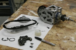
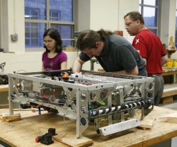
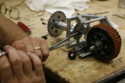
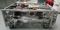
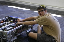
Pivot removed from robot
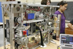
Pivotless robot - Andrew & Sasha in background
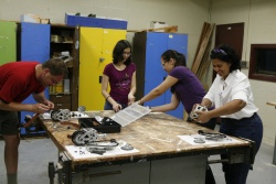
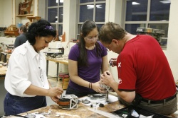
David Moyer, Nicole, Sasha & Rita Wall service pivots
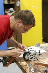
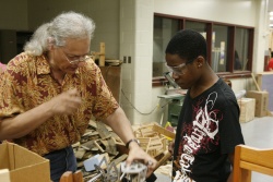
David Moyer retreading a pivot
Nicole, Mike Rizzo & David Moyer with robot
Rita Wall, Sasha & David Moyer retread wheels
Ben R programming Dewbot V

Return of the elusive Hans
Jon Davis & Garrison servicing worn pivots
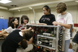
Nicole, Andrew, Carly, Sasha & Molly exchanging steering Victors for Jaguars
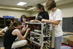
Nicole, Carly, Andrew, Sasha & Molly exchanging steering Victors for Jaguars
Gary Deaver servicing pivot
Matt, Faith McKown & Garrison servicing pivots
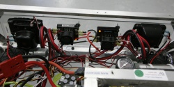
Victors replacing steering Jaguars
DEWBOT reassembled & Victors replacing steering Jaguars


Possessor
We've got a adequate possessor for demonstrations. At PARC, Monty Madness and (BR)2, we were dissatisfied with our possessor's performance. While it seemed to perform well enough at the STEM Defined demonstration, in the heat of competition, it tends to either fail to possess the ball, or to cause or allow the robot to drive over the ball. We really cannot effectively herd balls into the goal either (because of a tendency to drive over them). This is an area which needs work for IRI. Options seem to be:
- A vacuum possessor (like Team 25's)
- A Possessor with a low roller
- Adapt the possessor to grab the ball by pinching it (without lifting it off the floor) rather than just applying a backwards spin
Vacuum Possessor
- Preliminary analysis in Inventor indicates that it is feasible to accommodate a vacuum-type possessor similar to Team 25's in the DEWBOT VI chassis. The driver would have to accurately center the ball. Analysis and design were not pursued past this point.
Low roller Possessor
- We've observed that robots with effective possessors often have passive rollers at or below the ball centerpoint. Installing such a low roller on DEWBOT VI without a major redesign is not trivial. Key challenges are:
- Avoiding interference with the kicker
- Avoiding interference with the pivots
- Maintaining our ability to cross bumps without difficulty. A low-position roller intrinsically is in the way when climbing a bump
Trirol Possessor Design
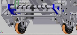
- A possessor was designed having an articulated, low, 3rd roller.
- The low roller is a ½" steel rod (like the middle roller)
- The low roller is set in needle (roller) bearings for free rotation
- The low roller articulates by pivoting forward and up out of the way for bump crossing.
- Two 3/4" diameter x 4" stroke pneumatic cylinders provide the actuation. Both run from a single solenoid. Restrictor valves will need to be installed on the solenoid vents.
- A hard stop is provided for the possessor in the lowered, working position (the design does not rely on the pneumatic cylinders to provide this stop). This hard stop is necessarily quite close to the pivot axis.
- While rotating between the deployed and retracted states, the low possessor assembly does not break the frame perimeter.
- It is proposed that the low possessor will automatically retract when the operator relaxes the kicker to cross a bump; and automatically deploy when the kicker is armed; normal kicking will not change the possessor state.
- In addition, it is likely that the combination of reversing the driven possessor and retracting the lower possessor roller would be a useful, low-velocity means to positively eject balls into the goal from the goal's ramp (without having to drive the robot entirely into the goal).
- The kicker is modified by having its lower portions cut away so that it clears over the 3rd roller.
As designed, this is a back-rolling possessor, not a pinching possessor. It could in principle be converted to a pinching possessor if the low roller bearings were removed or disabled.
View the detailed drawings.
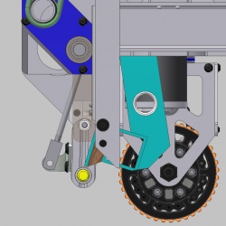
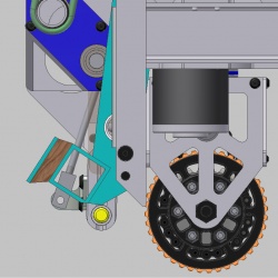
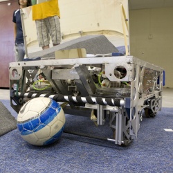
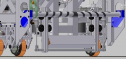
View of possessor with bottom roller in working (deployed) position
Detail of bottom roller articulation mechanism
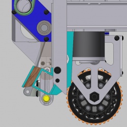
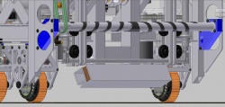
View of possessor with bottom roller raised (retracted) for crossing bumps
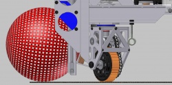
Side elevation with parts made invisible showing position of ball relative to the possessor elements
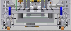
Front elevation
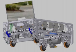
Robot view
Kicker close approach to 3rd roller - 1/3 - kicker boot
Kicker close approach to 3rd roller - 2/3 - closest approach
Kicker close approach to 3rd roller - 3/3 - maximum extension


Prototype Testing
- At Jon Davis's suggestion, a fixed 3rd roll prototype was installed and tested on 30-June. Key observations:
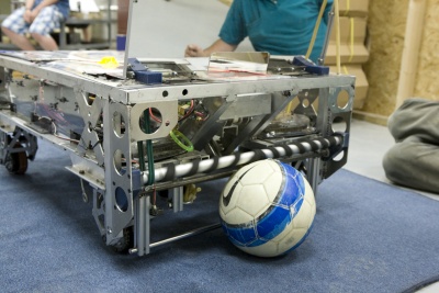 3rd roll prototype installed on DEWBOT VI
- Possession performance appears unaffected by the 3rd roller - poor-to-mediocre
- On the other hand, it is now impossible to override the ball
- and herding now works very well, possessor on or off

- Overall, some small improvement, but not at all what we were hoping for.
- Adding friction tape to the bottom roller resulted in no observable improvement.
Hi/Lo Roller Pinching Possessor test
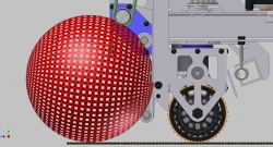
- We were planning to replace the middle steel roller with fiberglass, but before installing the fiberglass rod, we tested the possessor without the middle roller. This provided a phenomenal improvement in possessing performance. This Hi/Lo 2-roller possessor really works! It hangs on to the ball. The Hi/Lo 2-roller possessor is definitely a pincher. The bottom roller needs to be high-friction and needs to not roll easily (or at all). The bottom roller also needs to be stiff (so steel is better than fiberglass). No ball overdriving problem. The possessor will lose the ball if the ball touches the Ball Dam Gussett on either side. Transverse driving is therefore a problem if taken too far, but it can also serve to center the ball. We tested filling in the top roll spiral gaps with friction tape, but this had no obvious effect. Existing spirals are definitely not beneficial (they do not center the ball), but don't seem to hurt performance either.
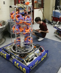
Testing the Hi/Lo 2-roller possessor
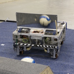
Testing the Hi/Lo 2-roller possessor - note ball in mirror view
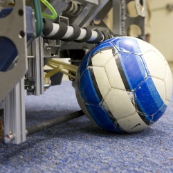
The ball never leaves the floor
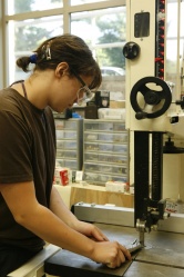
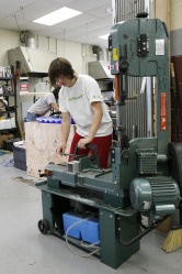
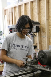
Heather McKown cutting parts

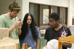
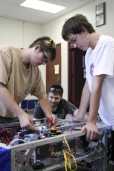
Paul, Kenneth, Siri Maley & DJ testing the possessor


Back to the Drawing Board (3 & 4-July)
- The elimination of the middle roller makes access for actuation of the low roller simpler. Narrowing the top roller is no longer necessary. A design with this change was started, then abandoned. The possessor went through two major redesigns in two days.
- Our tests make it clear that a great deal of backwards force is applied on the low roller. The Trirol's low roller mount was not designed with this sort of force in mind. We therefore need a more robust approach for the articulated low roller.
- In light of this need for robustness, we started investigating vertical retraction (linear motion) design. Robust linear motion 80/20 roller wheel assemblies (80/20 part # 2751) were gallantly liberated from DEWBOT IV. Mounted on the existing 80/20 kicker spring mounts, a quick prototype test indicated promise. CAD design and physical prototyping and testing ran together in parallel. The revised design is simpler, more easily executed and more robust. Things are still tight and require careful design and fabrication. Key points:
- The low roller is no longer intended to roll. No bearings provided.
- The (2) 3/4" diam x 4" stroke pneumatic cylinders will still be employed (they have already shipped, so this is good)
- The actuators will act in the direction of linear motion. Actuators will be hard-mounted (not pivoting).
- Actuator mounts are moderately complex and must be welded to the chassis frame
- The low roller is further forward and, when lowered, expected to occupy a lower position than the Trirol low roller
- The height of the low roller will be mechanically adjustable
- When retracted, the low roller mechanism will be entirely within the ball dam gusset envelope and therefore protected from impact with the bump
- The kicker width will be reduced from 15" to 13". The cutting of the lower extremities of the possessor for clearance will be less extreme than for the Trirol design
- The pinching design puts a lot of stress on the possessor drive motor and the polycord drive belts. We destroyed the original motor in testing.
- Regarding the last of these points (the excessive load on the possessor motor & drive):
- Our first thought was to limit current to the motor via a current-based feedback loop (a control/electronic solution)
- but an alternative approach would be to reduce the friction coefficient or the normal load between the possessor drive belt and either the motor pulley or the possessor tube, turning this into a poor man's clutch. This would continue to apply pinching force while at the same time avoiding motor stall, motor burn-out, excessive battery drain, and polycord melting. for example:
- reducing polycord tension by slightly increasing the belt length would reduce normal loads; while
- a different surface on either the pulley or possessor tube could reduce the friction coefficient;
- this approach could allow us to keep unloaded possessor velocity high, provide force for pinching; preserve the motors and drive parts; save battery power; and limit force on the low roller.
- The Possessor is effectively narrower.
- Additionally, benchmarking of other successful bottom rollers (which neither roll nor facilitate rolling) revealed an inordinate number of teams using 1/2" angle. Prototyping (with aluminum) seems to reveal why. The ball tends to roll (and thus fall out) much less than with even the misnamed bottom roller bar, and holds somewhat better in snake and much better in strafing. (Strafing is a beneficial aspect of our drivetrain could prove very helpful on defense against a certain looper bot at IRI.) The system isn't yet to death-grip standard, but I (Siri) wouldn't be overly surprised if changing the roller(s) surface(s) and/or speed (recommended at 2x robot speed) got us quite close.
- We appear to be having sporadic DS-robot communication malfunctions, both during bootup and randomly mid-test. It'd be great to determine the root cause(s).
Heather McKown preparing to cut 3" square tube on bandsaw for actuator mounting
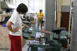
Heather McKown cutting 3" square tube on bandsaw for actuator mounting

Clem McKown building new possessor CAD model in Autodesk Inventor
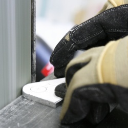
Heather McKown finishing an actuator mount on the belt sander
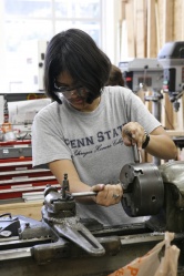
Siri Maley setting the low roller into the lathe
Siri Maley cutting low roller end to accept actuator clevis
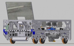
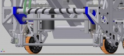
Robot with low roller retracted & kicker relaxed
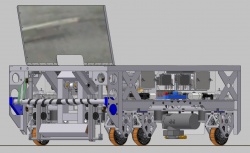
Robot with low roller extended & kicker relaxed
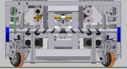
Front elevation - low roller extended & kicker relaxed
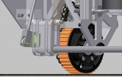
Front detail with low roller extended & kicker relaxed
Front detail with low roller retracted & kicker relaxed
Side elevation with low roller extended & kicker at ball contact position


Mirror
Looks really good, but we should:
- Verify that it stays within the frame perimeter.
- It would be good to have a means of raising it during competition. A servo might be adequate.
- A working possessor, or a sensor to kick automatically would be a benefit now that we can find the hidden balls.
3-July Update
- The mirror was moved back 1" to keep it within the frame perimeter (Jen).
- Initial prototyping and CAD took place for a servo raise/lower mechanism (DJ).
4-July Update
Much effort - little progress. Servos do not appear to have the necessary torque to raise the mirror.
Plan B would be to use a 3/4" pneumatic actuator.
photo gallery
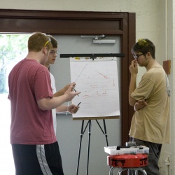
Cole, Douglas & Matt working on the plan of attack
Matt & DEWBOT VI
Matt, John Stumpo & Douglas working on mirror lift
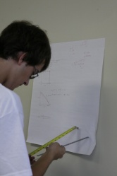
Douglas doing the math behind the mirror lift


Autonomous
Not effective yet. Main points seem to be:
- Sensor for kicking does not seem to be reliable.
- Angles for off-axis shooting need to be checked. They appear to shoot off-field is the robot is aligned to drive along the central ball column. I'll check, but we should test too.
- Keeping in a straight line by blind dead reckoning is often ineffective.
- Keeping the possessor off seems to work better (insofar as something which doesn't work can be said to work better).
- My initial angle calculations for autonomous were incorrect, as observed at (BR)2. My bad. the real angles can be found (with math) in Auto Angles (xls format).
- Without special (BR)2 rules, reasonable autonomous sequences are:
- Autonomous Near Field - choice of either:
- Set ball C2-R2
- Set wheels to 30° CW
- Set robot to drive down C(olumn)2 (use tape guide on robot top for alignment)
- Stop after 1 kick (not critical)
- or:
- Set ball C2-R2
- Set wheels straight with Calibration (delay is beneficial here)
- Set robot to drive through ball towards goal
- Stop after 1 kick (critical)
- Autonomous Mid-Field:
- Set balls at C2-R3 & C2-R2
- Set wheels to 9.5° CW
- Set robot to drive down C2 (using a 2nd guide tape)
- Autonomous Far-Field
- Set balls at C1-R3, C1-R2 & C1-R1
- Set wheels to 2.5° CW
- Set robot to drive down C1
- Where not specified, wheels should be pre-calibrated, wheel angles pre-set, and kicker pre-armed by tether prior to the match. This requires planning with alliance partners before queuing up for the next match.--Clem 1-June-2010
Catch up on other team information at FRC Team 1640