Talk:DEWBOT VII Philadelphia Regional
Contents
- 1 Preparation - To Do List for Thursday
- 1.1 Prioritization
- 1.2 Switch from Pulley to Chain Drive
- 1.3 Put on Competition Claw
- 1.4 Switch Compressors
- 1.5 Turn around Minibot Deployment
- 1.6 Mount Hangar
- 1.7 Install Torsion Brace
- 1.8 Mount Camera
- 1.9 Mount sonar sensor
- 1.10 Check pivots
- 1.11 Test all sensors
- 1.12 Adjust sensitivity of line-following sensors
- 1.13 Test Fangers
- 2 Post-Mortem
- 3 Execution on Action Plan
Preparation - To Do List for Thursday
Add part locations (probably the spare parts box), hardware and tools, etc.
Can we estimate how long each of these changes will take, or have a time to shoot for? --Julie
- What did we say, Clem? Pulley-Chain 30min; Deployment 20min; Compressor, Brace, Hangar 10min/ea; Camera & Pivots 5-15min/ea? Thursday-time, that is. - Siri
Is the BOM up to date for all these (minus compressor), or would you like a hand? - Siri
Prioritization
- Best to practice with ASAP (in order)
- Pulley to Chain Drive
- Mount sonar (test autonomous)
- Mount camera (test on FMS)
- Turn around deployment
- Competition Claw & Torsion Brace (nice but not necessary)
- Must be done before inspection
- Switch Compressors
- Mount Hangar
- Pivot check (ensure no inspection-worthy changes)
- Technically ok post-inspection
- Full pivot check
- Test all sensors
- Tune line-followers
- Tune arm PID (but would also be nice for early practice)
- Test Fangers (inspected separately)
Switch from Pulley to Chain Drive
- Remove arm drive motor assembly from arm column, cutting the belt
- Unbolt arm angle sensor mount; remove arm sensor
- Remove elastic counterbalance
- Unbolt lower bar pillow blocks
- Unbolt lower bar at triangle
- Remove lower bar
- Unbolt (2) ¼"-20 bolts securing 56T HTD5 pulley; remove pulley from lower bar
- Replace pulley with 42T sprocket/hub assembly; align key with keyway perpendicular to the ¼" mounting holes
- Insert lower bar axle back into pillow blocks
- Rebolt pillow blocks to columns
- Rebolt lower bar end to triangle
- Restring elastic counterbalance (5 passes); secure elastic using wire-ties out of the sprocket path
- Remove arm drive motor from mounting plate & bearing block
- Remove Remove 20T HTD5 pulley from arm drive gearbox shaft
- Install ½" ID x 0.32" PVC spacer on arm drive gearbox shaft
- Install 9T #35 sprocket (McMaster-Carr part # 6280K311 - bored thru to ½" with 1/8" keyway) with sprocket end towards the motor (hub end towards the shaft end); use a 3/32" key
- Install (1 or) 2 ½" Nylon Washers on the arm drive gearbox shaft outboard of the 9T sprocket
- Place the bearing block on the shaft end
- Drape the prepared 59-link #35 chain loosely on the 9T sprocket
- Bolt the arm drive motor/gearbox/bearing block assembly to the arm motor mount plate using (6) 10-32 x 0.50" FHCS
- Loosely secure the Arm Motor Mount to the column using (7) 10-32 x 2.00" FHCS & nylocks
- Secure the 59-link chain around the 42T sprocket with a master link; master link clip facing away from the lower bar
- Pull down on Arm Motor assembly to tighten chain (rotating arm to take out slack on both sides)
- Remount arm sensor mount
- Support the lower bar parallel to grade (use a spirit gauge)
- Reinstall & Calibrate encoder
- Check/set preset heights (floor, low, mid, high--HOW?)
(Tape measure + Ben or mark a couple PVC banner stand pipes. I'll document the heights Saturday. Don't know how/how crowded the practice field will be. - Siri)
As long as the encoder is calibrated where level is 90 degrees, there shouldn't be much change to the arm angles for the preset heights. --Julie
(So run a practice match and then see? Works for me. I'd still like those heights for reference though. Do we have them or should I measure? - Siri)
We've never had heights, just arm angles. --Julie - Tune PID
- Attach rear chain guard
- C-clamp side chain guard, drill new hole & bolt on
Put on Competition Claw
Time: <5min
- Unscrew jam nuts at linkages & unplug pneumatics
- Screw in Competition Claw's jaw nuts at linkages & plug in pneumatics
- Test floor height and wrist & jaw actuation.
- Any time: put on longer start position Velcro. (But always take off the bungee cord before the match!)
Switch Compressors
On standby pending Q&A
Suggest we pre-mount the compressor on new cross-bars at DRC. In mounting this to the robot, use one set of existing holes; use the holes in the mount bar as a template for drilling the two new holes needed. - Clem
That was my plan (hence "new bars with compressor"), but I don't know how rigid the orientation is. I remember with the Thomas's old standoffs, squaring the mounting was kind of annoying. Looking at the diagrams we should be fine, but if it's in Saturday I'll try it. - Siri
- Unscrew compressor mount bars
- Unplug pneumatic hose, disconnect wires and remove compressor
- Bolt in new front/rear mount bar (with compressor attached) and clamp rear/front bar in place. (I'll pick which when I finish CADing the new assembly (pending GDC cutting us a break) - Siri)
- Drill (2) new mount holes for bar that's shifting. (Do we need to tap those holes? - Siri) (Are existing holes tapped? - Clem) (I'll check Saturday - Siri)
- Screw in new bars with compressor & plug in pneumatic hose & connect wires (Do the wires disconnect compressor-side on both and/or do you know how to do this? - Siri)
- Test
Turn around Minibot Deployment
- Unscrew Bident & staff and pull out
- Unscrew back plate (with cylinder). Ensure pneumatic hoses are labeled.
- Unscrew Standoffs (keep rollers on them)
- Put jig in place & drill new Standoff & back plate holes
- Screw Standoffs & back plate in place. Ensure back plate is within frame perimeter. Ensure rear-most rollers are off-centered towards the robot front (as far from the Bident as possible, or it may go outside of the frame perimeter).
- Screw the new Bident & staff into the cylinder. Ensure Bident is in frame perimeter.
- Wire tie the pneumatic tubes so they can't be pinned by the retracting cylinder.
Mount Hangar
- Put on top edge clamp (4 bolts)
- C-clamp bottom angle in place. Ensure Hangar is in frame perimeter.
- Drill bottom angle mount holes in frame perimeter & bolt (3 bolts)
Install Torsion Brace
- Install top brace clamp (8 bolts)
- C-clamp bottom plates in place & drill H holes in frame (4 total)
- Bolt bottom plates in place (4 bolts)
Mount Camera
- Drill mount holes (2 holes, on reverse deployment jig)
- Mount camera & plug in (wire tie wires)
- Mount iron sight (needs jig)
- Test/calibrate
- Remove old camera mount
Mount sonar sensor
- Remove and unwire one front Sharp IR sensor
- Mount and wire one sonar sensor
- Test
- Update BOM accordingly
Check pivots
- Check nylock nuts for nylon engagement. If they do not engage the nylon, remove and loctite.
- Fix broken/disengaged shaft collar. Check other collars for engagement on the shaft and tightness. Add plastic spacers (same as Duex) and wire tie.
- Check pulleys. Raise if necessary, add spacers and wire tie.
- Check chain & belt tightness and wheel turning. Loosen CIM if drive is too stiff.
- Check sensor stand offs. Are they bent or showing signs of damage?
- Check treads. Make decision when to change. Check for bolt stripping throughout and determine how long change would take.
- Modify chain guard to fit with hangar.
- Test (Optional: color/tape 1 triangle on black pulleys for visual confirmation)
Test all sensors
Time: 5 minutes
- Run Testboard VI to check that all sensors can be read (this includes digital encoders).
- Run Testboard VI to check that all sensors can be read (this includes digital encoders).
Good call. Time? (All your guys know how to do this, right?) - Siri We should get the VI on your computer as well. --Julie
Adjust sensitivity of line-following sensors
- On real field if possible, ensure that photoelectric sensors indicate no signal (green light) on carpet and signal (yellow light) on grey tape.
Test Fangers
- After set of fangers pass inspection, test each one manually on the field poles. Make any fine tuning adjustments. Rank fangers for performance.
Post-Mortem
- Okay. We won. Why a post-mortem? To learn and to do things better next time.
What worked?
- Perseverance
- Flexibility
- Fanger and deployment
- Robot robustness & reliability
- Pivot drive (when mojo available)
- The pit
- Arm changes since Finger Lakes
- Media and pivot display
- Alliance negotiation & selection (a new realm for us)
- Never hurts to be lucky!
What could have been better?
- Autonomous - Needs calibration - eliminate oversampling
- There is no switch to turn Autonomous on and off
- Noise reduction
- <1/2 the tube scoring than at Finger Lakes
- Need better drive team performance
- Drive team critique must go through the coach
- Stronger grip on claw
- It would be very beneficial to be able to lift the claw (for defensive play)
- More robust claw needed
- Fanger deployment improvement for rough play (improved late at competition--would be needed for Mighty Mouse)
- The pit
- Scouting coordination
Action Plan
Mechanical
- Rebuild deux (Clem McKown lead)
- Build Claw II (Ben Kellom lead) - better grip - less floppy - tuck in?? - sensor?
- Design/build a faster Minibot (Mighty Mouse) (Gary Deaver lead) - to use same launch pad - lighter - faster - legal
- Toe-in test for autonomous
- Speed up deployment (Clem McKown lead) - split deployment cylinder extension and retraction to two solenoids to allow depressurization of the retraction side prior to actual deployment
Programming
- Reliable autonomous - all modes
- Off position using current switches
- Eliminate dead time during switch between crab & snake modes
- Is there a benefit to keeping the compressor off during autonomous?
Drive Team
- Directed, coached (Clem McKown or Siri Maley) Driver Practice - as much as possible!
- Defensive opposition-force robot with coached (Mike Rizzo), trained driver
Execution on Action Plan
Accelerated Minibot Deployment
- A fast Minibot is of limited value if the deployment is slow. In the original Bident pneumatic system, used at Rochester & Philadelphia, extension and retraction were accomplished via a single, single-acting solenoid. Pretty standard stuff. But slow, requiring 1.58s (σ = 0.08s) to fully deploy (all measurements taken on deux with 5 samples). Contributing to the slow deployment speed is the need to vent the retraction-side air through the solenoid's restrictive orifice.
- An alternative pneumatic arrangement was tested using two solenoids decoupling extension & retraction. Prior to actual deployment, the retraction side of the deployment cylinder would be vented (solenoid activated). Then the extension side pressurized for deployment (solenoid activated). Finally, deactivating both solenoids retracts the deployment cylinder. Deployment time dropped to 0.84s (σ = 0.1s). A good start, but the need to vent retraction-side air (even though no longer under pressure) through the solenoid with its small Cv slows extension and makes the movement uneven.
- A third arrangement was tested. Returning to a single solenoid, the retraction side of the cylinder is open to vent. This output on the solenoid is plugged. Only the extension side is powered. Faster deployment at 0.50s (σ = 0.1s). A normally-closed (NC) manual valve on the solenoid extension-side vent prevents Bident extension prior to deployment (due to the vacuum which any extension would create). The Bident must be retracted manually by opening the NC valve and pushing in the Bident.
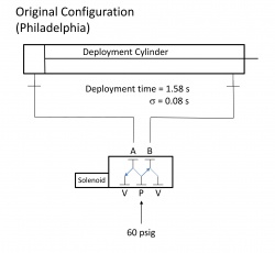
Original pneumatic system, used at Rochester & Philadelphia
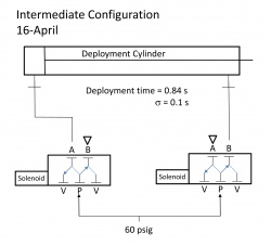
Interim design utilizing decoupled extension & retraction solenoids
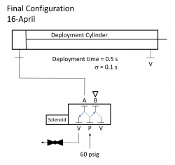
Final schematic, requiring manual retraction


Claw II
An improved claw was built for DEWBOT VII. The lower part of the Claw was not significantly different from the earlier Claw, but it is formed from a single piece of ¼" polypropylene, whereas the previous claw was a composite assembled from several pieces. In addition, formed flanges provide additional stiffness (eliminating the need for an aluminum rib) while lightening holes manage mass. Ben Kellom was the responsible mentor. Molly the student lead.
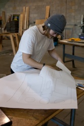
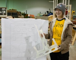
Molly cutting template for Claw II
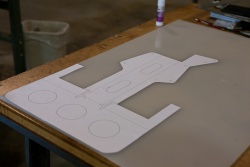
Claw II template on polypropylene
Polypropylene cut
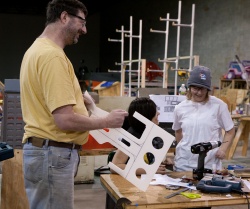
Molly holding the formed lower claw
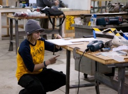
Cutting a 2nd
Claw II on deux


Mighty Mouse
On April 16 mighty mouse was constructed and at 10:35 PM was launched for the first time. It's fast. Direct drive 118 style with a weight of 2Lbs 1 OZ and 3/8" tubing on the fangs. More testing will be needed on Sunday April 17. The down side to direct drive is stall and the motors smoke. Durability of the cantilevered drive will be found.