Difference between revisions of "DEWBOT IX Drive Train"
MaiKangWei (talk | contribs) (→Pivot Module 9) |
MaiKangWei (talk | contribs) (→End-of-Season Perspective) |
||
| (48 intermediate revisions by the same user not shown) | |||
| Line 1: | Line 1: | ||
| − | == | + | [[Image:2013_pivot.jpg|right|frameless|upright=1.1|alt=2013 pivot (Solidworks)]] |
| − | + | [[image:DB9_SCH_130315_csm-10.jpg|right|frameless|upright=1.1|alt=DEWBOT's got places to go!]]Due to the anticipated strong defensive nature of Ultimate Ascent, the team decided on 11-January to utilize [[4-Wheel Pivot Drive | pivot drive]] again. In addition, to maximize agility, this drive would utilize our new Ocelot control code. | |
| − | |||
| − | |||
| − | |||
| − | + | ==Issues with the 2012 pivot design== | |
| − | |||
| − | |||
| − | |||
| − | |||
| − | + | Our 2012 robot, [[DEWBOT VIII]], participated in more competitions, demos and driver practice than any robot before it. In addition, barrier crossing (which we did often) was abusive to pivots and the robot in general. That said, the 2012 pivots generally performed very well, but the following issues were observed: | |
| − | [[ | ||
| − | + | :# Pivot tubes were not secure within the pivot tops and shifted over time. Small and mostly angular shifts resulted in loss of calibration. Large shifts caused pivot failure. This problem was resolved during the season by welding the pivot tubes to tops. | |
| + | :# The BaneBots RS-540 motors used in 2011 were not legal in 2012, so RS-395 motors were used instead. These motors are sufficiently powerful, but have very weak and easily damaged mounting points. The gearbox mounting plates for these motors also cover the front cooling ports, leading to easy burn-out. We literally ‘’burned’’ through a lot of RS-395’s in 2012. | ||
| + | :# Steering motor replacement required a significant disassembly of the pivot module. This was annoying in 2011 with the RS-540 motors, but became a crisis in 2012 with the 395’s requirement of frequent replacement. | ||
| + | :# Pivot module bottom plates tended to bend in service. The 5<sup>th</sup> bolt hole for securing this to the robot chassis was almost never used. | ||
| + | :#Set screws securing the 18T and 56T HTD5 pulleys to the CIM and coaxial drive shaft, respectively, did not reliably secure these pulleys. This never resulted in a loss of drive power, but was troubling. | ||
| − | + | ==Value Engineering== | |
| − | + | [[image:Value_Engineering.jpg|300px|right]]Value engineering seeks to widen the gap between the value a product provides to the customer and its cost. Value and cost in this context includes both monetary and non-monetary measures. For example, addressing the issues listed above increases the value of the product to the customer (drive team & pit crew). Cost includes monetary cost (measured following FRC cost guidelines) but also mass, manpower and machine time. | |
| − | + | Each Autumn, we conduct a value engineering exercise on our pivot drive design to understand what changes we would make if we were to select pivot drive again. The results of this exercise are summarized in the accompanying Table. | |
| − | |||
| − | + | ==Developments on the 2012 pivot design== | |
| + | [[2013 Pivot Development | Development]] of the 2013 pivot design took place through a number of physical tests and engineering exercises during the latter half of 2012. | ||
| − | + | The following design changes were made: | |
| − | + | :*Switched back to BaneBots RS-540 motor (legal again) in lieu of RS-395 | |
| − | |||
| − | |||
| − | |||
| − | |||
| − | |||
| − | |||
| − | |||
| − | |||
| − | |||
| − | |||
| − | |||
| − | |||
| − | |||
| − | |||
| − | |||
| − | |||
:*Replacing 35 chain with 25 chain - 9T & 24T sprockets replaced with 12T & 32T - 44 link 25 chain reduces pivot cage height | :*Replacing 35 chain with 25 chain - 9T & 24T sprockets replaced with 12T & 32T - 44 link 25 chain reduces pivot cage height | ||
| − | :*Change wheel to AndyMark 4" HiGrip Wheel (am-2256) - 32T sprocket secured w/ 10- | + | :*Change wheel to AndyMark 4" HiGrip Wheel (am-2256) - 32T sprocket secured w/ 10-32 x 5/8" SHCSs - No sprocket spacers needed |
| + | :*Adopted the VexPro 32T sprocket | ||
| + | :*Replace top 1" ball bearing race with Igus polymer bushing | ||
:*Narrow pivot cage from 4" to 3.184" - machined acetal spacer eliminated - shorter axles | :*Narrow pivot cage from 4" to 3.184" - machined acetal spacer eliminated - shorter axles | ||
:*Pivot tube designed to be welded into the pivot top | :*Pivot tube designed to be welded into the pivot top | ||
| Line 50: | Line 32: | ||
:*Elimination of (1) of (2) E-clips on the pivot tube | :*Elimination of (1) of (2) E-clips on the pivot tube | ||
:*Reduce spacer length between module plates to 1.75" (2" in 2011; 1.875" in 2012) | :*Reduce spacer length between module plates to 1.75" (2" in 2011; 1.875" in 2012) | ||
| − | |||
:*Use Deaver steering motor attachment | :*Use Deaver steering motor attachment | ||
| − | :* | + | :*E-clip securing the 56T HTD5 pulley |
| + | :*Reduce pivot mount points from (5) to (4) and replace locknuts with rivet nuts on frame | ||
| + | :*7075 Al replaced 6061 in the pivot braces and the module top plate | ||
| + | :*Redesigned module bottom plate to provide additional strength (and look cooler) | ||
| + | |||
| + | ==Ocelot Drive== | ||
| + | {{#ev:youtube|Pej5pkFvFdY|300|right|Ocelot Drive}}The most exciting change in the 2013 drive-train had nothing to do with the pivot mechanism, but rather with the software controlling it. | ||
| + | |||
| + | When we first developed pivot drive, we understood that it offered the potential for [[Media:Pivot_-_Crab_with_a_Twist_edit2.pdf|dynamic driving]] in addition to straight-forward crab & snake drives. Up until now, however, we have not been able to realize this potential and have managed with static drive modes (where joystick position maps directly to wheel positions). | ||
| + | |||
| + | Senior programmer Dhananjay (DJ), with help from mentor Gary Deaver, wrote the LabView vi for Ocelot drive. Programming Lead Mike M integrated the code and streamlined the wheel positioning to be resource practical on the cRIO. | ||
| + | |||
| + | A great job and great teamwork! | ||
| + | |||
| + | ==Pivot Module [[media:Swerve_1640_2013.zip | CAD Design]] and [[media:Swerve_BoM_2013.xls | Bill of Materials]]== | ||
| + | |||
| + | ==Calibration - no change from [[DEWBOT VIII Drive Train#Pivot Calibration | last year's]]== | ||
| + | |||
| + | ==Chassis & Wheel-base== | ||
| + | Chassis was once again welded 6061 Al. Mostly 1" x 2" x 0.130" U-Channel. | ||
| + | |||
| + | Wheelbase is 21" (nominally wide) x 22.25" (nominally long). Chassis exterior dimensions are 27.75" x 27.75". | ||
| + | |||
| + | ==Post-Championship Perspective== | ||
| + | Now that the robot's been through 44 qualification and 28 elimination matches, how have things help up? Remarkably well. | ||
| + | *Lost one drive train chain during the last match at [[DEWBOT IX Hatboro-Horsham | Hatboro-Horsham]] (this did not seriously impede performance). Failure occurred because the master-link became disconnected. | ||
| + | *The 4" HiGrip wheels have worn. Some of these have been replaced. | ||
| + | *(2) steering motors have burned out. Neither failure occurred in a match. Steering motor failures occurred when steering motors were constrained while the motors were trying to turn the wheel to its set-point. | ||
| + | * The angle sensor on the pit display pivot failed. This has happened before. | ||
| + | |||
| + | We have modified the robot cart to allow the wheels to rotate (and spin) without constraint. This change has the additional benefit of allowing easier and faster drive train checks between matches. | ||
| + | |||
| + | All-riveted chains (without master links) have been purchased and are replacing the originals (generally at the same time as worn wheels are replaced). | ||
| + | |||
| + | '''''Ocelot drive is awesome in competition!''''' We were really hard to block and were able to play an active defense when appropriate. | ||
| + | |||
| + | ==End-of-Season Perspective== | ||
| + | [[DEWBOT IX]] participated in 11 competitions throughout the 2013 season and off-season; more than any previous [[FRC Team 1640 | 1640]] robot. | ||
| + | |||
| + | We were champions twice in-season ([[DEWBOT IX Mid-Atlantic Region Championship | MAR Championship]] and [[DEWBOT IX FRC Championship | Newton Division]]) and twice off-season ([[DEWBOT IX Battle-O'-Baltimore | Battle O' Baltimore]] and [[DEWBOT IX Duel on the Delaware | Duel on the Delaware]]) and were finalists at [[DEWBOT IX MidKnight Mayhem | MidKnight Mayhem]]. A really great season. | ||
| + | |||
| + | We played over 140 competition matches. We also did an enormous amount of driver training. This drive-train got used! | ||
| + | |||
| + | Out of ten (10) pivot assemblies produced, one (1) failed completely (at Battle O' Baltimore). The weld failed at the critical tube/top junction. | ||
| − | + | A second failed repairably (but was not repaired) when the miter gear on the bottom of the co-axial drive shaft came off. | |
| − | |||
| − | |||
| − | |||
| − | |||
| − | |||
| − | |||
| − | |||
| − | |||
| − | + | A third failed (and was repaired) when the needle bearings on the coaxial drive shaft seized (it is suspected that these were never lubricated during assembly). | |
| − | + | One additional steering motor failed off-season. | |
---- | ---- | ||
| − | [[Category:Robot]][[Category:DEWBOT IX]][[Category:Drive-train]][[Category: | + | [[Category:Robot]][[Category:DEWBOT IX]][[Category:Drive-train]][[Category:Swerve Drive]][[Category:Photo Galleries]] |
Latest revision as of 01:33, 19 February 2017
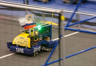
Due to the anticipated strong defensive nature of Ultimate Ascent, the team decided on 11-January to utilize pivot drive again. In addition, to maximize agility, this drive would utilize our new Ocelot control code.Contents
Issues with the 2012 pivot design
Our 2012 robot, DEWBOT VIII, participated in more competitions, demos and driver practice than any robot before it. In addition, barrier crossing (which we did often) was abusive to pivots and the robot in general. That said, the 2012 pivots generally performed very well, but the following issues were observed:
- Pivot tubes were not secure within the pivot tops and shifted over time. Small and mostly angular shifts resulted in loss of calibration. Large shifts caused pivot failure. This problem was resolved during the season by welding the pivot tubes to tops.
- The BaneBots RS-540 motors used in 2011 were not legal in 2012, so RS-395 motors were used instead. These motors are sufficiently powerful, but have very weak and easily damaged mounting points. The gearbox mounting plates for these motors also cover the front cooling ports, leading to easy burn-out. We literally ‘’burned’’ through a lot of RS-395’s in 2012.
- Steering motor replacement required a significant disassembly of the pivot module. This was annoying in 2011 with the RS-540 motors, but became a crisis in 2012 with the 395’s requirement of frequent replacement.
- Pivot module bottom plates tended to bend in service. The 5th bolt hole for securing this to the robot chassis was almost never used.
- Set screws securing the 18T and 56T HTD5 pulleys to the CIM and coaxial drive shaft, respectively, did not reliably secure these pulleys. This never resulted in a loss of drive power, but was troubling.
Value Engineering
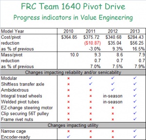
Value engineering seeks to widen the gap between the value a product provides to the customer and its cost. Value and cost in this context includes both monetary and non-monetary measures. For example, addressing the issues listed above increases the value of the product to the customer (drive team & pit crew). Cost includes monetary cost (measured following FRC cost guidelines) but also mass, manpower and machine time.Each Autumn, we conduct a value engineering exercise on our pivot drive design to understand what changes we would make if we were to select pivot drive again. The results of this exercise are summarized in the accompanying Table.
Developments on the 2012 pivot design
Development of the 2013 pivot design took place through a number of physical tests and engineering exercises during the latter half of 2012.
The following design changes were made:
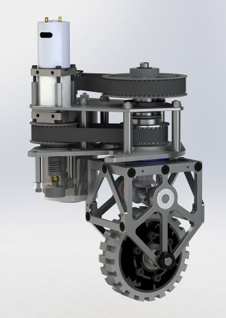
- Switched back to BaneBots RS-540 motor (legal again) in lieu of RS-395
- Replacing 35 chain with 25 chain - 9T & 24T sprockets replaced with 12T & 32T - 44 link 25 chain reduces pivot cage height
- Change wheel to AndyMark 4" HiGrip Wheel (am-2256) - 32T sprocket secured w/ 10-32 x 5/8" SHCSs - No sprocket spacers needed
- Adopted the VexPro 32T sprocket
- Replace top 1" ball bearing race with Igus polymer bushing
- Narrow pivot cage from 4" to 3.184" - machined acetal spacer eliminated - shorter axles
- Pivot tube designed to be welded into the pivot top
- Drive miter gear shortened axially by 0.25" - further reducing pivot cage height
- Elimination of (1) of (2) E-clips on the pivot tube
- Reduce spacer length between module plates to 1.75" (2" in 2011; 1.875" in 2012)
- Use Deaver steering motor attachment
- E-clip securing the 56T HTD5 pulley
- Reduce pivot mount points from (5) to (4) and replace locknuts with rivet nuts on frame
- 7075 Al replaced 6061 in the pivot braces and the module top plate
- Redesigned module bottom plate to provide additional strength (and look cooler)
Ocelot Drive
The most exciting change in the 2013 drive-train had nothing to do with the pivot mechanism, but rather with the software controlling it.When we first developed pivot drive, we understood that it offered the potential for dynamic driving in addition to straight-forward crab & snake drives. Up until now, however, we have not been able to realize this potential and have managed with static drive modes (where joystick position maps directly to wheel positions).
Senior programmer Dhananjay (DJ), with help from mentor Gary Deaver, wrote the LabView vi for Ocelot drive. Programming Lead Mike M integrated the code and streamlined the wheel positioning to be resource practical on the cRIO.
A great job and great teamwork!
Pivot Module CAD Design and Bill of Materials
Calibration - no change from last year's
Chassis & Wheel-base
Chassis was once again welded 6061 Al. Mostly 1" x 2" x 0.130" U-Channel.
Wheelbase is 21" (nominally wide) x 22.25" (nominally long). Chassis exterior dimensions are 27.75" x 27.75".
Post-Championship Perspective
Now that the robot's been through 44 qualification and 28 elimination matches, how have things help up? Remarkably well.
- Lost one drive train chain during the last match at Hatboro-Horsham (this did not seriously impede performance). Failure occurred because the master-link became disconnected.
- The 4" HiGrip wheels have worn. Some of these have been replaced.
- (2) steering motors have burned out. Neither failure occurred in a match. Steering motor failures occurred when steering motors were constrained while the motors were trying to turn the wheel to its set-point.
- The angle sensor on the pit display pivot failed. This has happened before.
We have modified the robot cart to allow the wheels to rotate (and spin) without constraint. This change has the additional benefit of allowing easier and faster drive train checks between matches.
All-riveted chains (without master links) have been purchased and are replacing the originals (generally at the same time as worn wheels are replaced).
Ocelot drive is awesome in competition! We were really hard to block and were able to play an active defense when appropriate.
End-of-Season Perspective
DEWBOT IX participated in 11 competitions throughout the 2013 season and off-season; more than any previous 1640 robot.
We were champions twice in-season ( MAR Championship and Newton Division) and twice off-season ( Battle O' Baltimore and Duel on the Delaware) and were finalists at MidKnight Mayhem. A really great season.
We played over 140 competition matches. We also did an enormous amount of driver training. This drive-train got used!
Out of ten (10) pivot assemblies produced, one (1) failed completely (at Battle O' Baltimore). The weld failed at the critical tube/top junction.
A second failed repairably (but was not repaired) when the miter gear on the bottom of the co-axial drive shaft came off.
A third failed (and was repaired) when the needle bearings on the coaxial drive shaft seized (it is suspected that these were never lubricated during assembly).
One additional steering motor failed off-season.


