Swerve Central
Contents
- 1 What is Swerve Drive
- 2 Benefits of Swerve Drive
- 3 Drawbacks of Swerve Drive
- 4 Design Considerations
- 5 Ocelot Drive (2013)
- 6 Thought experiment/Project: 3-Wheel Swerve (2013-2014)
- 7 Continuously Variable Transmission (CVT) Swerve (2017)
- 8 Driving Straight with Swerve (2018)
- 9 Wiring Harness (2018)
- 10 Pivot Calibration
- 11 FRC 1640 White papers and CAD Design
- 12 Value Engineering
What is Swerve Drive
In FRC circles, swerve drive can be used for any drive train in which all drive wheels are steered. For this forum, the definition will be restricted to drive trains where all drive wheels are independently driven and steered. It is a holonomic drive train in which the robot can move in any direction and independently translate its chassis orientation.
Benefits of Swerve Drive
- Agility - a true 2-d drive train in which drive direction may be divorced from chassis orientation
- Traction - in contrast to other holonomic drive systems, high traction wheels may be employed without negative consequence; furthermore drive force may be vectored in any desired direction
- Stealth - no need to telegraph intentions via chassis reorientation
- Flexibility - with the drive direction and power controlled independently to each wheel by software, multiple drive modes, including game-specific drive modes, become possible
- Dynamic Steering - for most FRC drive trains, driver joystick input maps 1:1 with drive train motor instructions; swerve steering directions to each wheel need not simply reflect driver joystick input, but may also reflect current "t" status in determining "t+δt" motor instructions; from a practical standpoint, this may be used as an agility force-multiplier; see Ocelot drive for clarification
- Minimal steering hysterisis - there is almost no need to overcome static friction in steering
- Servicability - an independent wheel drive train just screams modularity; 1640 can swap out a pivot module in < 5 minutes (easy peasy)
Drawbacks of Swerve Drive
- Complexity/difficulty - This is not an easy drive train to execute; mechanically or programmatically; not for the faint-hearted or impatient; it took us 4 years to realize all of the benefits (maybe, we think)
- Mass - 1640's reduced the mass of 4 pivot modules to 31.6 lbm. Still a lot for a drive train
- Time - CNC machining takes time; so does the assembly of complex mechanisms; as a result 1640 has finished swerve modules available to mount in chasses only at the start of week 5
- Cost - Financial cost of swerve modules is a significant (but fortunately declining) portion of our build budget
- Motor budget - 4-wheel swerve requires (4) drive motors and (4) steering motors; (8) motor controllers; (4) analog inputs; these leave less for other functions
- Difficulty in driving straight - Not so surprisingly, an ultra-agile drive train has trouble driving a straight line; drivers compensate in tele-op, but this is a particular issue with autonomous (solved in 2018)
- High use of cRIO resources
- Driver training is not optional with swerve. Frankly, we train all the time and participate in a lot of off-season competitions for real training. Use of OP-FOR robots on our practice field yields the dual benefit of making practice more realistic and training additional drivers.
Design Considerations
- Functional Specifications
- Maximum drive speed: 9.8 ft/s (2017 CVT swerve is significantly faster)
- Provide 130 lbf drive thrust at max power (less & variable for 2017 CVT Swerve)
- 1-2 rev/s steering speed w/ shortest path algorithm
- Capable of infinite steering rotation
- Drive direction must be known
- Pivot module must be replaceable (fully ready for competition) in < 5 minutes
- Drive wheel static friction coefficient > 1.0 on carpet (as high as practical) - all directions
- Rotational Steering Support & shear strength
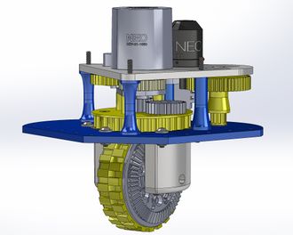
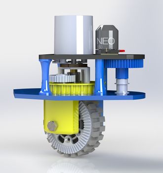
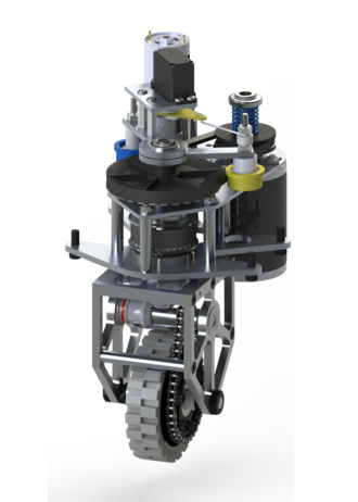
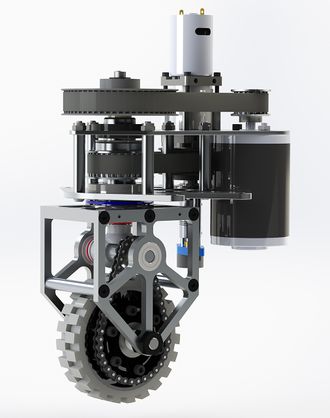
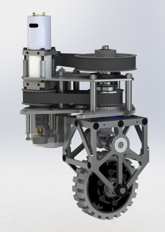
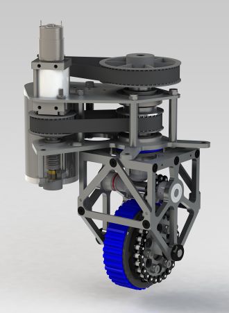
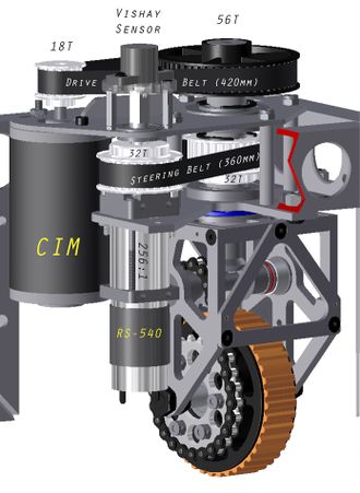
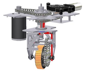
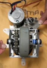
- Steering rotation axis is a 1" OD x 0.25" wall 6061 Al tube connected to the top of the rotating pivot cage. The wheel contact area is centered on the rotation axis. This steering tube is rotationally supported by two bearing surfaces separated by 1.388" between inner bearing limits; 2.326" between outer bearing limits. The lower bearing is a 1" double sealed, flanged ball bearing race (McMaster-Carr part 6384K373). The upper bearing was switched to a Igus polymer bushing in 2013 (happy so far). The bearings are mounted in the lower and upper pivot module plates.
- From a shear-load standpoint, the system's traditional weak point is the connection between the 1" OD steering tube and the rotating pivot cage top plate. These are currently groove-welded at the lower face. Hitherto (1 year), none of these welded connections have failed and we have yet to discover the new weak point (no failures due to shear loads/impacts).
- The 3/8" 4140 steel drive shaft runs coaxially within the 1" OD steering tube. Open needle bearings (McMaster-Carr part 5905K22) have been installed at the top and bottom of the steering tube for this drive shaft (for 4 years without issue). Lubricate needle bearings during initial assembly.
- Axial loads & thrust bearings
- There are three key axial loads, and we use thrust bearings for each of these:
- The junction between the top of the rotating pivot cage and the bottom pivot module plate. This bears the robot weight and takes any shocks from hitting/driving over objects on the field (like Frisbees). We use a 1½" thrust bearing (McMaster-Carr part 6655K25; we bag the top steel washer and let the ball run on the 1" flange bearing's flange.
- The two miter gears want to get away from each other in the worst way, thereby creating axial loads behind both of these. 3/8" shaft (McMaster-Carr part 6655K15).
- Lubricate all (3) thrust bearings during initial assembly.
- Rotational Axes
- We have (5) rotational axes: (3) vertical; (2) horizontal:
- The CIM motor (drive) axis
- The steering axis
- The pivot steering / drive co-axis
- The transfer axle; driven by miter gear and drives a sprocket (to drive the wheel)
- The wheel axle (a 3/8" dead axle)
- Modularity
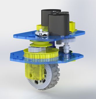
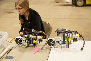
- Our pivots are designed for rapid replacement of the entire drive module for service. A pivot can be swapped out and replaced in less than 5 minutes. All pivot modules are identical (no left & rights) and all are pre-calibrated identically (relative to the pivot module). This is a tremendous competition pit time saver.
- Set screws
- They live to come loose. They do not belong on a swerve module, or any drive train. Learn (design) to live without set screws and you will be happier in competition.
Ocelot Drive (2013)
The most exciting change in the 2013 drive-train had nothing to do with the pivot mechanism, but rather with the software controlling it. Swerve drive works on software, after all.When we first developed pivot drive, we understood that it offered the potential for dynamic steering in addition to straight-forward crab & snake drives. Up until now, however, we have not been able to realize this potential and have managed with static drive modes (where joystick position maps directly to wheel positions).
Senior programmer Dhananjay (DJ), with help from mentor Gary Deaver, wrote the LabView vi for Ocelot drive. Programming Lead Mike M integrated the code and streamlined the wheel positioning to be resource practical on the cRIO. The full robot project code, including Ocelot drive, can be found in the FRC1640 2013 Competition Season Code repository on GitHub.
A great job and great teamwork!
Thought experiment/Project: 3-Wheel Swerve (2013-2014)
The 2013 change in perimeter rules (112 in overall perimeter vis-à-vis 28in x 38 in) opened up new potentials for non-rectangular robots.In particular, the new rules reduce the stability penalty of a 3-wheeled robot design vis-à-vis the preceding 28" x 38" chassis limits.
The team decided to explore this avenue as an off-season project. It actually occupied two off-seasons with work starting in 2013 and continuing in 2014. Urgency increased in 2014 with 6-CIM tank drive becoming established as the competitive standard. A good engineering project, but we never employed these learnings in a competition robot (yet).
Driver response was very positive.
Continuously Variable Transmission (CVT) Swerve (2017)
One drawback of swerve drive vis-à-vis tank drive is the relative penalty paid for incorporating gear shifting. Tank drive, with two independent powerplants, requires two gear shifting mechanisms; Swerve, with four independent powerplants, requires four. This is a serious design hurdle for a drive train which is already a little avoirdupois.
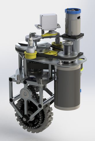
Fortunately, the team has worked to develop the employment of continuously variable transmission (CVT) as a means of employing variable gear reduction without excessive weight. By relying on pulleys, CVT fits 1640's swerve design philosophy far better than gear-based shifting. In fact, the fit is natural.
CVT was successfully employed from 2017 through 2020 (DEWBOT XIV, DEWBOT XV, DEWBOT XVI & DEWBOT XVII). Motor improvements (brushless motors) reduced the benefit gained with CVT and as a consequence, it was dropped after 2020.
- CVT Reduction
- In past swerve systems, reduction had been managed in two stages: a 3.11:1 1st stage reduction via HTD5 pulleys (18T & 56T) from CIM to coaxial drive shaft; and a 2.67:1 2nd stage reduction from the miter gear to wheel via sprockets and chain for a total reduction of 8.30:1.
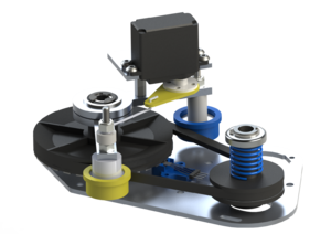
- The current system replaces the HTD5 pulley reduction with a spring-loaded constant velocity pulley (Torque Transmission VPS-15) and a V-belt pulley (Torque Transmission PO-3.5-3/8) connected with a V-belt (Gates 2L 180). The constant velocity pulley had a pitch diameter which varies between 0.9375 and 1.875 inches; the other pulley has a fixed 3.4 inch pitch diameter. These provide a 1st stage reduction which can be varied between 3.63:1 and 1.81:1. In combination with the old 2nd stage reduction, the overall reduction can be varied over the range 9.67:1 to 4.84:1.
- The constant velocity pulley comprises two v-pulley flanges forced together by spring loading. Under low belt tension, the pulley flanges remain together and the v-belt rides in the high-diameter position. As belt tension is increased, the pulley flanges are pushed apart, bringing the belt into a lower-diameter path. Since the drive pulley is constant velocity, increasing the belt tension increases the reduction ratio.
- The V-belt is tensioned variably using a servo which controls the positions of a pair of tensioning pulleys. The servo and tensioning pulleys are mounted on an upward extension of the coaxial drive shaft.
- In 2020, with the change to a low-profile swerve module, the CVT tensioning mechanism was changed. Instead of varying belt tension with a pair of pulleys, we used a servo to shift the axis of the drive motor, thereby changing the V-belt pulley-to-pulley centerline distance.
Driving Straight with Swerve (2018)
Two significant changes were made in the 2018 swerve modules which enable our robots to drive straight.- Commercial quadrapole encoders replaced the unconventional means for measuring distance and speed; and
- Most of the backlash is eliminated from the swerve steering mechanism.
Backlash in 1640's swerve were traced back to:
1) the reduction gearbox;
2) undersized keys on pulleys.
We have used 3-stage 132:1 BaneBot P60 gearboxes for steering since 2012 (DEWBOT VIII). These gearboxes are not re-used year-to-year, but are purchased new for each generation of swerve drives. The key cause of backlash in the P60 gearboxes is the double-D connection between the final planet carrier and the output shaft. This backlash tends to increase over time.
The team identified a 100:1 planetary gearbox (17HS19-1684S-PG100) from Steppermotorsonline.com with integral output shaft/planet carrier. This gearbox has extremely low backlash and testing in 2017 indicated that they were robust enough for FRC service. These gearboxes are purchased with stepper motors attached; these stepper motors are removed and replaced with AndyMark 9015 motors (mated via printed mounts). In spite of having to purchase and discard the stepper motors, this gearbox is a cost savings vis-à-vis the P60 it replaces.
The weak point of the new gearbox is its unfortunate D output shaft. A great deal of development went into making the connection to this D-shaft reliable and durable. This effort is likely to be ongoing.
An alternative gearbox for consideration is VexPro's Versaplanetary gearbox. These also have low backlash (with spline connections between output shaft and planet carriers and between stages). The form factor of the Versaplanetary offers challenges and it would add weight and cost to 1640's swerve modules.To reduce backlash at the pulley/shaft connections:
- The drive pulley is now printed with a 1/2" Hex hub. A 1/2" Hex shaft mates precisely with this pulley.
- On the driven side, a 1/4" key fits precisely in a keyway in the 1" pivot shaft. A printed pulley with a 1/4" broached keyway fits snugly over this.
We also aggressively stopped a bad practice of cutting keyways too small, thereby requiring keys to be sanded to fit. This poor practice led to systematically undersized keys. In addition to introducing backlash, these undersized keys had a tendency to fall out.
Wiring Harness (2018)
We took a serious effort in 2018 to sensibly organize the swerve wiring harness. While this had always been a consideration and has improved over the years, the 2018 swerve wiring harness can be considered to be designed.
Pivot Calibration
Pivots are calibrated to zero identically - relative to the pivot module. In this way, pivot modules may be exchanged or replaced without having to recalibrate. A great time saver!
FRC 1640 White papers and CAD Design
- Mathematical Analysis of the Pivot-Wheel System.
- Programming a Pivot Drive Robot.
- Mathematical analysis - Crab with a Twist.
- Mathematical analysis of 3-wheel swerve - The Trouble with Tribots
- CAD design of FRC 1640's 2022 swerve module - zipped SolidWorks files
- CAD design of FRC 1640's 2015 swerve module - zipped STEP format
- CAD design of FRC 1640's 2013 swerve module - zipped STEP format
- Detailed BoM of FRC 1640's 2013 swerve module
- CAD design of FRC 1640's 2012 swerve module - zipped STEP format
- Detailed BoM of FRC 1640's 2012 swerve module
Value Engineering
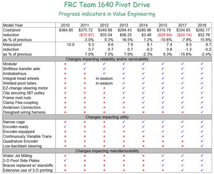
1640 has always viewed swerve drive as a strategic investment. While not the best drive train solution for all situations, it is a very attractive drive train for many FRC situations.But it's expensive (in many dimensions). 1640 therefore runs a value engineering project each year specifically for the swerve drive.
Value Engineering seeks to widen the gap between a device's value (to the customer) and its cost by:
- increasing the value (performance, reliability, ease of maintenance,...);
- reducing the cost (normally $s, but also mass, motors, time, driver training,...); or
- both
Results of value engineering efforts summarized in table at right with links to details below:
